Rapid prototyping for the 802.11 era
The 802.11 family of wireless local area network (WLAN) standards is becoming ubiquitous. Products for its various fl avors – up to and including its latest 802.11n incarnation – must reach the market as quickly as possible. This implies a need for rapid prototyping, typically on an FPGA platform.
This article describes how the design cycle for an 802.11 MAC was cut by using the Celoxica version of the Handel- C hardware description language (HDL), which narrows the gap between a design’s simulation and its implementation in hardware. It also reviews how quickly legacy code written in the C language can be migrated to Handel-C.
Today’s media access control layer (MAC) designs combine hardware, software and fi rmware. Most of the implementation is in software and fi rmware – only time-critical components are implemented in hardware. This approach satisfies timing requirements such as the Short Inter Frame Space (SIFS) in the IEEE 802.11 wireless local area network (WLAN) standard.
The hardware design cycle comprises simulation using a software tool (such as Matlab), fi xed-point evaluation and fi nally composition of the code in a hardware design language (HDL) (such as Verilog or VHDL) for synthesis.
This paper discusses an 802.11 MAC in which time-critical components are implemented on a Celoxica RC300 development board and a Xilinx Virtex 2 FPGA. It shows the structure of Handel-C code and how previously written C code is migrated to Handel-C with minor modifi cations.
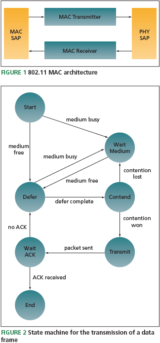
The main role of a MAC sub-layer is to provide addressing and channel access control mechanisms that help ensure reliable data communication over the noisy wireless medium. Figure 1 shows an 802.11 MAC architecture as a set of modular design blocks. The MAC service access point (SAP) and the physical layer (PHY) SAP are, respectively, interfaces between the MAC layer and the upper layer and the MAC layer and the PHY. The MAC transmitter provides a mechanism for reliable data transmission. The MAC receiver decodes packets received from the PHY and passes data to the upper layers via the MAC SAP. Control information is also conveyed to the MAC to increase transmission reliability.
A MAC’s core functionality is in its transmitter. The MAC is built around the process of obtaining access to the medium and transmitting data packets reliably. The 802.11 MAC employs Carrier Sense Multiple Access with Collision Avoidance (CSMA-CA) as its fundamental protocol (aka the Distributed Co-ordination Function (DCF)). CSMA-CA allows a network of nodes to share a wireless medium in a distributed manner.
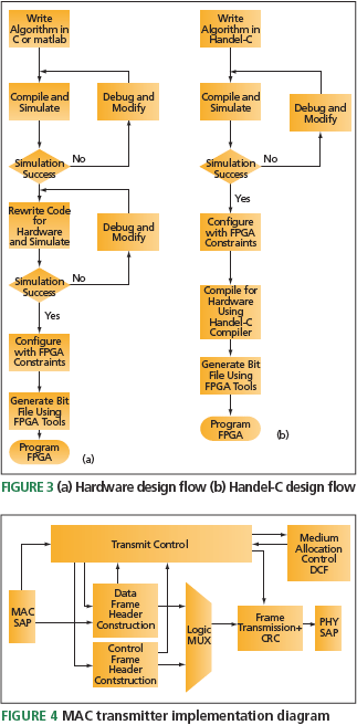
The fi nite state machine in Figure 2 defi nes how a node transmits a data packet with the simplest CSMA-CA (i.e., excluding the Request To Send/Clear To Send (RTS/CTS) handshake protocol). When sending a data packet, a node listens to the wireless medium. If another device is using the medium, the node waits until it becomes free, then moves into the defer state. The defer state allows prioritized channel access by imposing different defer times (inter-frame spaces (IFS)) to different transmission types. Ongoing frame exchange sequences use Short IFS (SIFS), allowing them to control the medium until they complete. The DCF IFS (DIFS) is used when initiating transfer of a data packet and the Extended IFS (EIFS) timer is used when a packet decode fails.
If the medium is still free after a DIFS period, the node contends by choosing a random number of back-off slot periods. This minimizes collisions as it is unlikely that multiple nodes will choose the same number of slots. The node counts down the back-off slots and if the medium remains free, the packet is transmitted.
If the medium becomes busy before the end of the contention window because another device chooses a smaller window, the device loses the contention period. It must return to the defer state when the medium becomes free. On re-entering the contend state, the device continues its back-off slot countdown from where it previously left off. This continues until the back-off slots have been counted down and the packet is transmitted.
To confi rm the successful transfer of a packet, the sending node waits for an acknowledgement (ACK) after transmission. This ACK signifi es that the frame exchange sequence is complete. If no ACK arrives within a specifi ed time, the packet is assumed lost and the device attempts to resend it.
Handel-C
Figure 3a depicts an FPGA design flow. A design is simulated in software then rewritten and simulated for hardware before configuration and programming onto the array. Figure 3b shows how using Celoxica’s Handel-C and its design environment cuts development time by eliminating the need to rewrite code in an HDL.
Handel-C is a variant of C used to describe an algorithm that is directly compiled to an FPGA or output at RTL for synthesis. The Handel-C development kit enables simultaneous hardware/software co-design, partitioning and effi cient profi ling. It also allows system co-verification, supporting cycle-accurate simulations of C, C++, SystemC, Handel-C, RTL and Instruction Set Simulator (ISS) models. This increases productivity and cuts time-to-market for complex projects.
Implementation
Figure 4 shows the implementation of a MAC transmitter as a set of modular design blocks. The transmit control acts as a scheduler, enabling effi cient transmission of data and control packets. The medium allocation control block performs the DCF for channel access. Two blocks construct headers for data and control frames. Finally, a frame transmission block computes the cyclic redundancy check (CRC) and transfers the MAC frames to the PHY via the PHY SAP. Each block is coded and tested independently before integration into the transmitter.
The design’s modular nature and Handel-C’s use of macro procedures facilitate easy coding and test for individual blocks. The transmit control, medium allocation control (DCF) and the CRC encoder form the most important blocks in the MAC transmitter. They can be used to illustrate how a design is described in Handel-C and how easy it is to migrate from C to Handel-C.
Transmit control
This is the master controller responsible for the generation and transmission of data and control frames. Its functions include:
- providing triggers to the various blocks for generating a frame, obtaining medium access and frame transmission;
- examining packet sizes to decide if an RTS/CTS mechanism should be deployed before sending the data;
- setting retransmission triggers if no ACK is received;
- resetting DCF and discarding packets if a positive ACK is received or the limit on retransmissions is reached; and
- setting the EIFS timer if packet decoding fails and resetting the timer if a good packet is received.
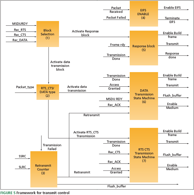
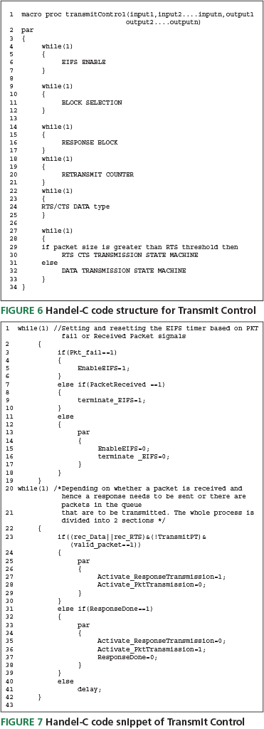
Figure 5 shows the transit control framework. It consists of seven design blocks running in parallel and has two state machines that generate the necessary control signals for a simple frame exchange sequence (FES) with and without RTS/CTS. It has switches for activating the state machines depending on the required protocols, and a response block to provide the necessary triggers for control frame generations. Finally, it has a design block to activate and deactivate the EIFS timer for DCF.
Handel-C code structure
Figure 6 shows the Handel-C code structured as seven independent processes running in parallel. The design block is written as a macro procedure in Handel-C (Line 1). This is similar to a C function call. The inherent parallelism of hardware is exploited by Handel-C using the ‘par’ construct, which allows multiple processes to run in parallel.
The ‘while’ statement illustrates a process that runs forever and is operated by a clock. Figure 7 shows a section of the transmit control code for illustration. The code snippet is for the EIFS enable and block selection design.
The fi rst ‘while’ loop is used to set and reset the EIFS timer based on failing or passing packets. This is done with a simple ‘if else’ (Lines 1-19). The second ‘while’ loop checks at every clock cycle if a packet is received and is valid. It then decides to activate either the response block or the packet transmission block. Line 23 of Figure 7 performs this check. The ’||’ symbol represents an OR operation and ‘&’ represents an AND operation. These operators are the same as used in C.
Medium allocation control
This block (aka the DCF mechanism) implements CSMA/ CA access. It is activated by the ‘enable medium’ trigger from the transmit control block. The process begins by sensing the channel, and completes by sending an ‘access-granted’ trigger to transmit control.
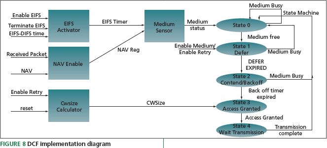
Figure 8 shows the DCF implementation as fi ve design blocks running in parallel. The EIFS Activator and NAV enable blocks aid the medium sensor in assessing its status (‘busy’/‘idle’). The CWSize calculator block is used to calculate the contention window size in the event of retransmissions. The state machine has global control and performs the DCF operation as explained above.
Handel-C code structure
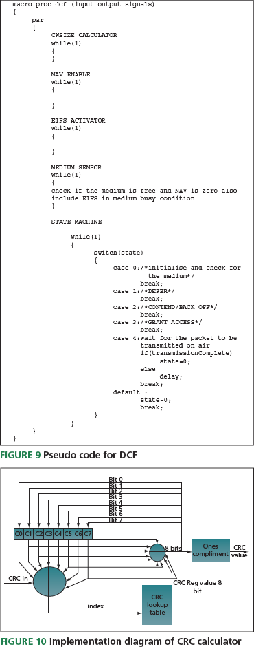
Figure 9 presents the pseudo code for the DCF block. It consists of four processes running in a parallel state machine. The above two code examples demonstrate that Handel-C is a high-level language similar to C that abstracts the user from low-level design issues. These are dealt with by an environment that optimizes the design for hardware.
CRC encoder
To ensure reliable reception, 802.11 MACs validate received data using cyclic redundancy checks (CRCs). This function takes a variable-length data stream as its input and produces a fi xed-size output. The CRC calculation is based on the polynomial specifi ed in section 7.1.3.6 of the standard.
Figure 10 shows the implementation of the CRC. It consists of two XOR gates, a lookup table and an 8bit register.
The incoming data is XOR’ed with the 8bit register initialized to all ones. The output gives the index of the lookup table as a pre-computed table of all 8bit entries of the CRC calculation shift register. Pre-computing these values saves much time. Calculating them in real-time for every packet consumes 256 clock cycles; fetching them from ROM takes one clock cycle. Hence a trade-off is made between memory usage and time.
The output of the CRC table is XOR’ed with the shift register, and the ones compliment of the last four bytes of the result gives the CRC value.
C and Handel-C code
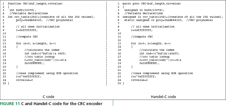
Figure 11 shows the C code and its Handel-C modifi cation. The very minor changes necessary are:
Line 1: the C function call is replaced by Handel-C’s macro procedure.
Lines 3-6: the variable declaration ‘int’ is changed to ‘unsigned 32’
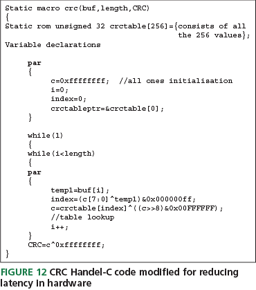
The C code can be run in hardware. However, it is sequential and would run slowly. Handel-C exploits the inherent parallelism of hardware and allows the code can be further modifi ed to operate at a faster clock rate (Figure 12). As seen from the code, it is fairly simple to convert the existing C code for software to Handel-C code for hardware design. Hence, rapid prototyping in hardware can be achieved by using existing C code as a starting point.
Conclusion
The results of the coding methodology outlined herein were subsequently evaluated both in software (using Mentor Graphics’ Modelsim) and in hardware (on a Celoxica RC300 board) and produced satisfactory results in both environments. The design of an 802.11 MAC transmitter using Celoxica’s Handel-C was presented. The methodology of migrating software code written in C to hardware was presented using the CRC encoder as an example. Experimental results in both simulation and hardware were presented for a two-node network scenario. It was deduced that by using Handel-C, a design can be evaluated in software and hardware with minor modifi cations, bringing major benefits for rapid prototyping and time-to-market.
Telecommunications Research Laboratory
Toshiba Research Europe
32 Queen’s Square
Bristol
BS1 4ND
T: +44 (0) 117 906 0700
W: www.toshiba-europe.com/research