New breed of SPYDER discovered
Freescale Semiconductor manufactures some of the industry’s most widely used microcontrollers.
The article describes the functionality behind the new Background Debug Module that has been developed for its 8 and 16bit MCUs.
The BDM provides all that is needed to write, compile, download, in-circuit emulate and debug code, when deployed in conjunction with the well-known suite of Code Warrior development tools.
It also does this at very low cost and in a form as portable and easy to use as a USB stick.
The HC05 and HC11 8-bit cores, introduced in the 1980s, were widely used by all segments of the market. In the late 1990s the HC08 (8-bit) and HC12 (16-bit) cores arrived and became more popular for niche applications. In early 2000, the HCS12 16-bit core, followed by the HCS08 8-bit core, was introduced with a key new feature on the Background Debug Module (BDM) making development work with these MCUs easier.
Figure 1. Core roadmap
The 8-bit HCS08 and recently introduced RS08 microcontroller (a reduced HCS08 core made physically smaller by, among other steps, removing instructions) contain a single-wire background debug interface, supporting in-circuit programming of on-chip nonvolatile memory and non-intrusive debug capabilities. It is this BDM connection that enables the release of low-cost, easy to use tools. It is also present on the 32-bit microcontroller 68K/ColdFire V1 core products, being introduced this year (see roadmap in Figure 1).
In 2005, freegeeks.net provided the HCS12 microcontroller com-munity with an open source debugging interface called TBDML. It was downloaded almost 1,500 times in its first 12 months online, demonstrating that engineers found it very valuable. Freescale has now made an equivalent tool available for our 8-bit, BDM-enabled microcontrollers. It is available in two forms:
- Open Source BDM (OSBDM) for the HCS08. Details of this can be found on Freescale Forums (http://www.freescale.net/forums). This self build tool costs less than $10 and can be bought pre-fabricated.
- The USBSPYDER08 Development Kit. This supports the MC9S08QG, MC9S08QD and MC9RS08KA 8-bit microcontrollers, and will also support future Freescale 8-bit 8-pin MCUs.
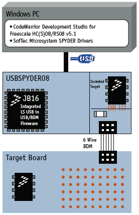
OSBDM and USBSPYDER08 essentially do the same thing, although the focus here will be on the latter. They interface between the Windows PC development environment and target MCU (Figure 2). The main purpose of these tools is to provide the market with a very low-cost and easy-to-use design option.
USBSYPDER08

Figure 2. Block diagram

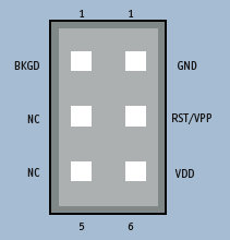
Figure 3. BDM Connector
USBSPYDER08 is a USB-to-BDM development tool and was built by SofTec Microsystems with full support from Freescale. Together with the well-known CodeWarrior, it provides all that an engineer needs to write, compile, download, in-circuit emulate and debug code. It also does this in compact form. The USBSPYDER08 uses a low-speed USB interface and is provided in the form of a standard flash memory stick.
If you are not familiar with BDM, it is Freescale’s equivalent to ICD, debugWIRE, or JTAG for use with our most recently launched families of 8bit and 16bit MCUs. The BKGD (BacKGrounD) pin on these devices provides a single-wire background debug interface to the on-chip debug modules. While the interface is single wire (typically a 6-pin connector), a BDM port is used to interface with the target (Figure 3).
The primary function of this pin is for bidirectional serial communication of active background mode commands and data transfer. During reset, this pin is used to select between starting in active background mode or by launching the designer’s application program. Additionally, this pin requests a timed sync response pulse, allowing a host development tool to determine the correct clock frequency for background debug serial communications.
Background debug controller (BDC) commands are sent serially from a host computer to the BKGD pin of the target HCS08 or RS08 MCU. All commands and data are sent most-significant-bit-first using a custom BDC communications protocol. With a single-wire background debug interface, it is possible to use a relatively simple interface pod to translate commands from a host computer into commands for the BDC.
In the case of the USBSPYDER08, full-speed program execution allows developers to perform hardware and software testing in real time. The tool works at bus speeds up to 10MHz, supports the 3.3V operation range of the MCUs, and has a socketed target MCU on board that can be replaced with other supported PDIP-packaged parts available in small sample quantities. To increase the flexibility of the tool, there is a BDM connector for off-board debugging of the supported products in other packages or where development work requires the incorporation of other board components.
Usage
The USBSPYDER08 tool relies on the HCS08 and RS08 BDC module to enable the fast and easy programming of the on-chip flash and any other memories. It is the primary debug interface for development, allowing non-intrusive access to memory data and traditional debug features such as CPU register modify breakpoint, and single-instruction trace commands.
The tool uses its USB interface to communicate with the PC and takes the USB bus voltage as its own power supply and that for the microcontroller, making it truly portable. This USB power supply can also power the target board, up to a motor capacity of 100mA.
The heart of the tool is the MC908JB16 MCU. It has a USB 2.0 low speed interface and operates from the 5V supplied by USB. When the tool is used for RS08 MCUs, 12V is needed for programming. The tool’s MCU recognizes the target device and via control of PTD0 can deliver the 12V signal using the DC-DC converter chip.
1. Board Assembly
The essential parts of the USBSPYDER08 are already populated on the product, allowing it to be used as a stand-alone tool with the socketed micro. If the designer needs to use another package type or a separate target board, this is also possible. By adding a 0? resistor or a short circuit on the space next to the bed of nails labeled R2, the power supply is connected to the BDM socket so you can use another target board. The net result is that the tool turns into a BDM pod.
2. Debugger Installation
The Special Edition of the CodeWarrior Development Studio for Freescale HC(S)08/RS08 v5.1 is provided free-of-charge on the USBSPYDER08 CD (more information on the features of this tool is available at www.freescale.com/codewarrior). Without a license key, the product will run in a 1KB code-size limited demonstration mode. To go beyond the 1KB limit, there are two options:
- Contact Freescale to request an unlimited period, free license key to increase the code size limit to 16 KB.
- Contact Freescale to request a 30-day limited, free license key to run the compiler without limitations.
3. Drivers
Once the board is ready for development, CodeWarrior is installed, and the next step is to make the USBSPYDER08 communicate with the debugger. After the drivers have been installed from the accompanying CD and the tool is connected to a PC for the first time, Windows will recognize a new USB device. At this point the ‘Windows New Hardware Wizard’ dialog box will open and asked for the required driver. Now, the user only needs to choose the ‘Install Automatically’option
4. Ready to Start Discovering
USBSPYDER08 uses the target MCU to execute the in-circuit execution, not an emulator. So, the microcontroller’s peripherals (e.g., Timers, A/D converters, Serial Communication Modules etc.) are not reconstructed by software or an external device.
To create a new project for any of the devices the tool supports, the engineer needs to start the process in CodeWarrior. From its main menu, select ‘File > New Project…’ or from the startup box click ‘Create New Project’. A dialog box will then appear prompting the user to select the target device from a pull down menu. Select ‘SofTec HCS08’ as the connection type. Then set the code type, project name and location. If there are no files to add and you do not want to use the device initialization tools, then press ‘Finish’. CodeWarrior will create the project, set up the framework for the code and include the header file which has all the register definitions.
Once you have written code and are ready to start debugging, ‘make’ the file and then ‘compile’. You can do this by either using the shortcut buttons in the main window, opening the ‘Project’ drop-down menu, or by pressing ‘F5’ then ‘F7’.
The first time the debugging session is entered an ‘MCU Configuration’ dialog box will open, prompting you to select the debugging hardware connection to your PC. Make sure that the connection type ‘USBSPYDER08’ is selected. At this point CodeWarrior has erased and reprogrammed the memory and trimmed the oscillator, if the feature is available on the selected MCU.
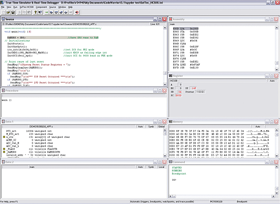
At this stage you have everything you need to start debugging code. CodeWarrior offers several ways in which to analyze program flow via breakpoints, watchpoints and a trace buffer. All these features are implemented by taking advantage of the target microcontroller’s debug peripheral. Figure 4 shows the CodeWarrior window. This consists of:
- A source window with your code displayed;
- An assembly window where you can see what the compiler has created from your source code;
- A registers window where the CPU registers are visible;
- A memory window where you can watch any location or force bytes to another value;
- Other windows with data, procedures and commands.

Figure 4. CodeWarrior window
The format of the data and the refresh rates of the data can be changed by right clicking on the window and changing the mode or format. Preferred settings can be saved by going to
‘File > Save Configuration’.
Engineers new to CodeWarrior should take a few minutes to familiarize themselves with the ‘Start/Continue’, ‘Single Step’, ‘Step Over’, ‘Step Out’, ‘Assembly Step’, ‘Halt’ and ‘Reset Target’ buttons. Application notes AN3335: “Introduction to HCS08 Background Debug Mode” and AN2616: “Getting Started with HCS08 and CodeWarrior Using C” are good resources when learning about the debugging environment.
The bed of nails next to the MCU can be connected to a scope to allow monitoring of the pins out with the debugger, in real time.
Summary
The USBSPYDER08 Discovery Kit has been developed as a flexible tool that meets low budget developments requirements. It supports Freescale’s 8-pin S08 devices with the ability to extend pin count using the off-chip target option.
Freescale Semiconductor Inc.
6501 William Cannon Drive
West Austin TX
78735
USA
T: 1 800 521 6274
W: www.freescale.com