How to create adaptors between modeling abstraction levels
The article is abstracted from a presentation given at NASCUG by Umesh Sisodia and originally developed by Ashwani Singh of CircuitSutra Technologies on how to create adaptors between various modeling abstraction levels in SystemC.
Adaptors that enable a mixing of the abstraction levels in SystemC offer a number of benefits. In particular, they make it easier to develop virtual platforms quickly because designers can reuse existing models across multiple levels rather than having to create dedicated ones for each.
SoC modeling
Any intellectual property (IP) that is modeled consists of three components:
- The behavior—the actual functionality of the IP.
- The communication—the protocol through which the IP communicates with the rest of the components in an SoC.
- The timing.
“These three components are separate from one another and, generally, will be modeled separately so as to allow the maximum code reuse across the abstraction levels,” Umesh Sisodia explained to the NASCUG audience. “So when we create the model, depending on the use case, it has to be designed at a particular abstraction level. The abstraction level mainly depends on two things: how much of the timing accuracy is modeled and how much of the data accuracy is modeled.”
Levels of abstraction
There are several types of terminology used to define the abstraction levels. CircuitSutra uses that developed by OCP-IP as part of its transaction-level modeling (TLM) kit. The various levels of abstraction are shown in Figure 1.
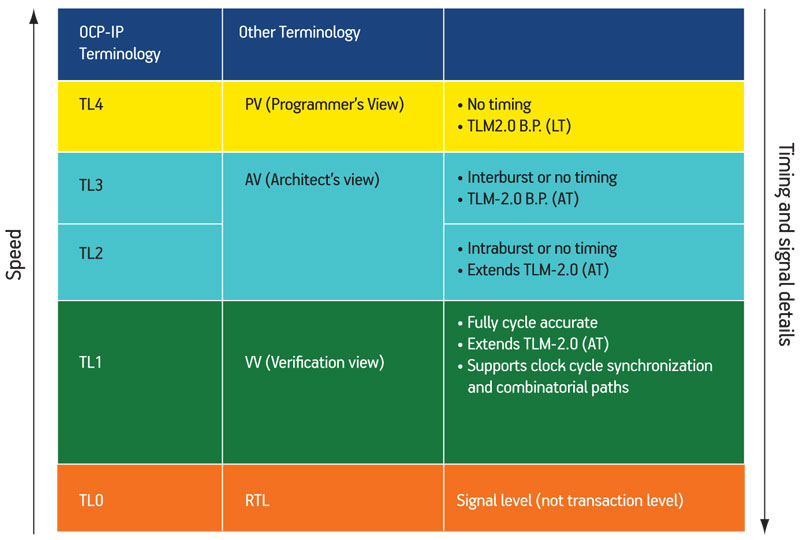
Figure 1
Levels of modeling abstraction
- TL4 is the highest. It is similar to a Programmer’s View abstraction level and akin to the loosely timed methodology defined in the TLM2.0 base protocol.
- TL3 is similar to an Architect’s View and akin to the approximately timed methodology defined in the TLM2.0 base protocol.
- TL2 is also a use case for an Architect’s View but is defined by extending the approximately timed methodology in TLM2.0.
- TL1 is a fully cycle-accurate abstraction level also implemented by extending TLM2.0, and it supports clock cycle synchronization and the combinatorial path. Given its most frequent use, it is alternatively known as a Verification View.
- TL0 has the greatest similarity to RTL in that it is a model incorporating signals and pins.
The difference between TL3 and TL2 can largely be explained by the fact that TL3 supports inter-burst timings and TL2 supports intra-burst timings; every bit of the burst can be modeled separately in TL2.
In the case of TL1, it is also similar in many ways to an RTL model, but it offers a transistor-level rather than pin-level model.
As the user works with higher abstraction levels in this hierarchy, the speed of simulation increases and the accuracy of timing and data decreases.
Adaptors
As you would expect, adaptors come into play when the engineer seeks to mix different IPs at different abstraction levels in the same platform. “Let us say that we are creating a platform at the TL4 level for embedded software development but we don’t have models of all the IP at that level and we don’t have time to make them,” Sisodia said. “We can take the models from the RTL at TL0 level by using some tools, and in that case an adaptor is required to plug the TL0 model into the TL4 platform. Obviously, the speed of the simulation will go down but, as you progress, those [TL0] models may be capable of being replaced with actual TL4 models.”
Alternatively, he described a scenario where a company already has some models defined at one or several abstraction levels but wants to create a virtual platform at another level. “Instead of creating models from scratch, they might use adaptors so they can use their existing models. And then by using combinational adaptors and transactors in the existing SystemC environment, they can be mixed in with advanced RTL for hardware-software coverification.”
Figure 2 shows a mixed-abstraction-layered system. The platform is being specifically developed at the TL4 level where both a master and a bus are available. Slave IP1 is at TL4 level and directly connected to the bus without any adaptor. Slave IP2 and Slave IP3 are at different abstraction levels and require adaptors. Finally, an adaptor and a SystemC-Verilog transactor are used to connect an RTL block, first by bringing it to TL0 and then adapting it into the system.
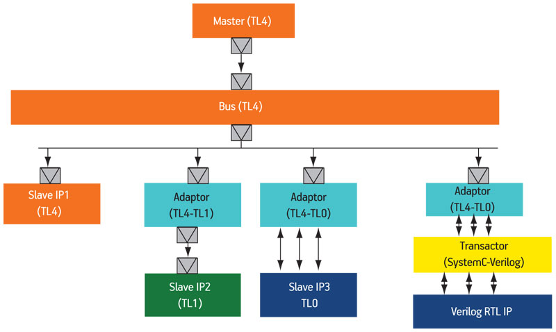
Figure 2
Mixed-abstraction-layered system
These adaptors can be used in both directions depending on the chosen abstraction level for the work. Where the master is at the higher abstraction level and the slave at a lower one, the adaptor is considered ‘downstream’. Where the master is at a lower abstraction level and a slave at a higher one, the adaptor is considered ‘upstream’.
Adaptors in practice
Handling timing abstraction
“At higher abstraction levels, we have less timing accuracy and fewer timing points. At higher abstraction levels, we have more timing accuracy and more timing points within a transaction. The adaptor is supposed to take care of all of that,” explained Sisodia.
“In the case of a downstream adaptor, the adaptor is going to insert some timing points. In the case of an upstream adaptor, the adaptor is going to remove and abstract away timing points.
“Similarly, to represent the state of the system at each timing point there will be some data variables. At a lower abstraction level, because there are more timing points, more data variables will be required. Again, the adaptor has to take care of that. The downstream adaptor has to introduce the extensions and in the case of the upstream adaptor it has to abstract away those extensions.”
Figure 3 shows a TL2 master and a TL3 slave connected to an adaptor. At TL2, there is support for intra-burst timing and the bits of the burst can be modeled separately. At TL3 timing is inter-burst, so the entire burst goes in the same transaction.
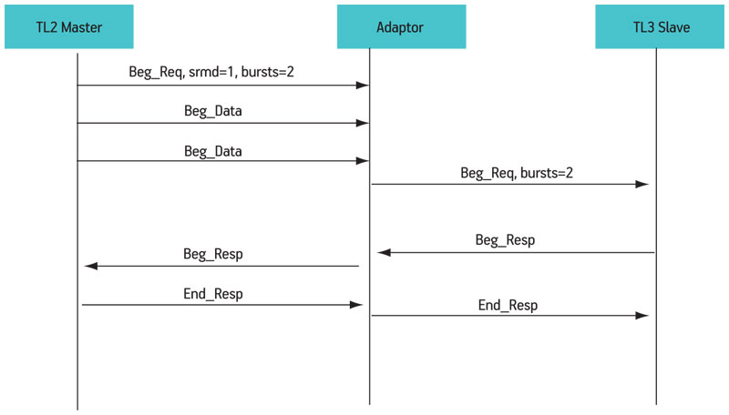
Figure 3
Handling timing abstraction: addition/deletion of timing points (phases)
“The OCP-IP TLM kit has extended OSCI TLM2.0 for these lower abstraction levels like TL2 and TL1,” said Sisodia. “They have introduced a new phase, ‘begin data’. So, for the first bit on the burst, this phase goes ‘Beg_Data’. In this case, there are two bits in the burst, so this happens again and the adaptor will not send a request to the TL3 slave unless it has received all the bits in the burst. Once it has, it will send the ‘begin request’ to the TL3 slave. And when it receives the response from the TL3 slave, it then sends the response to the TL2 master. That’s how we are able to abstract away these timing points.”
You could perform a similar process in the other direction with a TL2 master and a TL1 slave. TL1 is cycle accurate and has to model each word separately, but in TL2, the bit of the burst is modeled separately. So, the TL2 master will send a single request for two words but the adaptor has to then make two requests, one for each word of the TL1 slave. Here, the adaptor introduces timing points.
Handling payload extensions
The OCP-IP TLM kit provides a mechanism through which the TLM sockets can be configured. Through the configuration parameters, users can tell which different payload extensions are supported by each particular socket. When you connect the master to the slave, the system will check whether these are compatible and whether or not they support similar extensions. If they are compatible, the platform will work. If they are not, there will be some sort of error. The example in Figure 4 (p. 24) shows a scenario with different configurations. The TL1 master supports extensions A, B, C and E but the TL3 slave supports only A and E, so the adaptor has to abstract away B and C and do this at run-time.
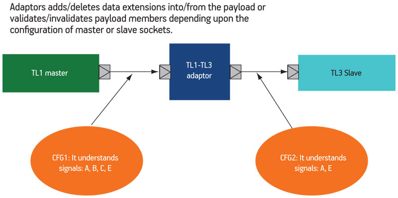
Figure 4
Handling payload extensions
Handling the order of transactions
Figure 5 shows a TL4 master and a TL3 slave connected to an adaptor. This TL4 master can generate multiple threads and multiple blocking calls, and the adaptor has to maintain the order of the transactions. Before the completion of the transaction generated by A1, A2 has initiated another transaction, so the adaptor maintains the state of both the transactions through some internal variables and preserves their order. In more sophisticated scenarios, this maintenance will also include blocking and non-blocking conversion, potentially from multiple sources at different levels.
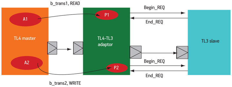
Figure 5
Handling order of transactions
Handling out of order transactions.
In Figure 6, a TL2 master and a TL4 slave are connected through an adaptor. The TL2 master can relay multiple transactions out-of-order—that is, before the first transaction has completed, it can generate another transaction. In this case because traffic is from a lower abstraction level to a higher abstraction level, the timing points have to be abstracted away. The adaptor has to delay the blocking call until it has received all the data phases for a particular transaction and thereby deal with the fact that these two transactions are happening in parallel.
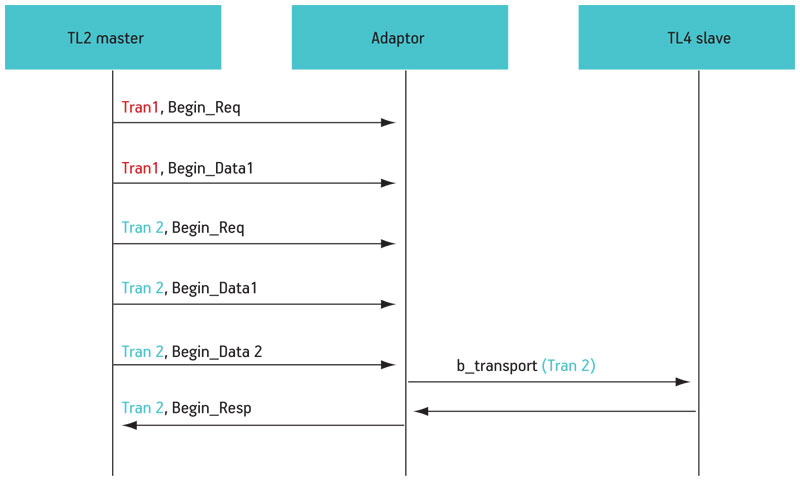
Figure 6
Handling out of order transactions
Conclusion
The presentation demonstrated the robust range of upstream and downstream adaptor technology now available to allow models to be combined across multiple transaction levels according to the main objectives behind the work from high level software development through to coverification. The adaptors smooth model reuse and thereby can greatly reduce the time and effort required to perform system-level simulations with SystemC.
CircuitSutra Technologies
Amity Innovation Incubator
E3, First Floor
Amity Univ. Campus
Sector-125
Noida-201301,U.P
India
T: +91-120-6515357
W: www.circuitsutra.com
Open SystemC Initiative
W: www.systemc.org