Efficient packet header parsing using an embedded configurable packet engine
Cswitch’s CS90 Configurable Switch Array device has an interconnect structure, the dataCrossconnect network, that delivers bandwidth at 40- 100Gbps for packet-based applications. For packet handling tasks, the chip includes embedded configurable blocks, Configurable Packet Engines, that support functions such as frame parsing, CRC and hashing, and fast address look-ups, all at up to 1GHz. For storing packets, the chip includes over 18Mb of on-chip memory and support for the latest high-speed memories. All these elements are completely configurable. Additionally, the chip includes look-up table-based logic that supplements these blocks.
This article discusses the CSA’s capabilities in terms of complex packet inspection and processing, and the Packet Parser CPE incorporated within the CS90. These are illustrated through implementations for a Q-in-Q Layer-2 application and an Ethernet generic-framing procedure (GFP) application in a metro networking context.
Introduction
The packet-based data transport infrastructure is growing at a rapid rate, driven by the digitization of everything from voice calls to music and movies. The consumption of these packets is increasing demand for bandwidth, but more importantly, it is driving the need for complex packet inspection and processing at every node in the infrastructure. As a result, equipment such as metro routers and switches, multi-service provisioning platforms (MSPPs), and reconfigurable optical add-drop multiplexers (ROADMs) now include packet processing capabilities.
Increasing this equipment’s packet processing capabilities means increasing data rates, but it also entails handling a growing variety of packet formats and evolving protocols, all of which must be resolved at rates set to enter the 40–100 Gbps range within three years.
Packet processing starts with an analysis of packet contents and the extraction of header information. This information is then used to make decisions regarding the packet, such as flow classification for quality of service (QoS), the access control list (ACL) and routing. Extracting header information requires flexible hardware, since the packet formats may differ across various applications. This article describes the capabilities of the configurable embedded packet parser block that is part of Cswitch’s CS90 Configurable Switch Array architecture, and how it can be used to implement a frame parser that meets the demands of next generation carrier products. The description focuses on the architecture of a packet parser that can perform complex packet analysis operations at wire-speed without compromising the high data throughput required by today’s infrastructure equipment. To illustrate, a Q-in-Q Layer-2 application and a Ethernet generic framing procedure (GFP) application in a metro networking context are described.
Packet processing overview
An ingress frame from theWAN is received by a 10G Ethernet MAC/PCS interface that forwards it to the packet parser. The packet parser analyzes the frame’s contents, extracts the fields necessary for ACL and flow classification, and then forwards the frame to a pre-queuing packet editor. The extracted header is sent to the classification engine. The classifier uses the parsing results to generate a key to perform lookup in a preconfigured TCAM-based policy database. The lookup result from the classifier (e.g., flow ID) is then sent to the pre-queuing packet editor where it is prepended to the original frame before being forwarded to the traffic manager for QoS queuing.
In the traffic manager, an incoming frame is received by the queue manager, which enqueues the new packet in external packet memory (typically DDR II) at a location in protocol data unit (PDU) memory as determined by the flow ID. Then, the queue manager notifies the scheduler that a new packet has been queued in PDU memory. It is now up to the scheduler to decide when the packet should be retrieved and transmitted to its next destination.
The scheduler may implement an algorithm such as Deficit Round Robin. Such algorithms are required to support differentiated QoS treatment and guarantee service level agreements (SLAs) that are critical for delay-intolerant services. A packet selected by the scheduler for transmission is de-queued through the memory controller and handed off to the post-queuing packet editor where packet encapsulation is performed before the frame is transmitted over the switch fabric interface.
Packet parsing
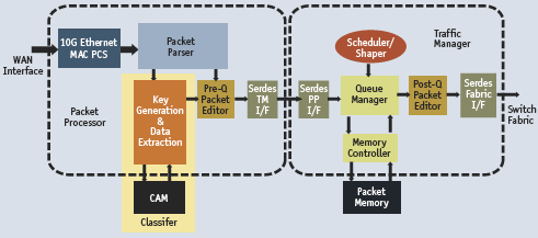
Figure 1. Common packet processing functions
The packet processor block in Figure 1 provides network termination (MAC), classification, and a pre-queuing packet editor. To classify and edit packet headers, information must be extracted by the packet parser function. The packet parser Configurable Packet Engine (CPE) in the CS90 device architecture specifically supports header extraction for any packet based on the OSI Reference Model, which defines the position of various protocol fields within a frame across three layers:
- Link layer: this defines fields associated with frame encapsulation such as Ethernet MAC addresses, Ether-type and the frame check sequence;
- Network layer: this defines the fields responsible for carrying routing information, such as the IP header which includes the source and destination IP addresses; and
- Transport layer: this defines fields associated with machine-tomachine information transfer, such as User Datagram Protocol (UDP) and the Transmission Control Protocol (TCP) headers which contain the source and destination port numbers.
Packet parser function architecture
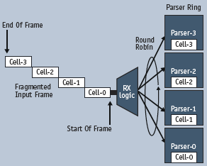
Figure 2. Parser ring configuration
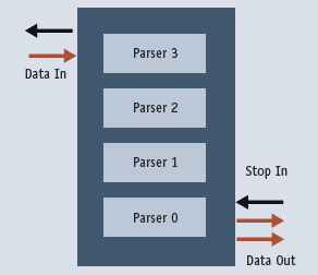
Figure 3.Parser ring flow control
Packet parsing is implemented in the CS90 by assembling CPEs in a ring. As a packet leaves the MAC, it is transmitted to the ring. The configurable ring input logic divides the input frame into cells for processing by individual CPEs within the ring. Cells are dynamically steered by the receive logic to individual parsers inside the parser ring using a ‘round-robin’ dispatching policy (Figure 2). Upon evaluation, the cells are shifted out of the ring, preserving order. The number of bytes in each cell and the evaluation criteria for the particular cell/field of interest are fully configurable, providing support for any type of packet-based protocol. A packet parser implemented in a CS90 device can be customized to perform many frame processing functions, including:
- Frame header analysis;
- Frame header fields modification;
- Frame header fields extraction;
- Payload data modification (up to 256Byte in standard parsing mode);
- Payload data extraction (up to 256Byte in standard parsing mode);
- Payload data modification (up to Nx256Byte in recursive parsing mode); and
- Payload data extraction (up to Nx256Byte in recursive parsing mode).
Moreover, with its ability to randomly inspect frame content and analyze frame headers, the packet parser can be used as a frame classifier or packet switch. For example, a parser can classify incoming frames by inspecting the payload-type indicator field. If this indicates the frame carries user payload traffic, it is forwarded through the normal fast path where it may end up in the external packet buffer awaiting to be scheduled. However, if the parser determines that the frame carries management information, it may be re-routed or switched directly to the host interface via a dedicated Gigabit Ethernet port – also known as a management port – for further analysis and action by the host processor.
When parsing is complete, the results are prepended to the original input frame and sent to the classifier with pre-queuing packet editor functions being implemented elsewhere.
If required, the CPE ring can output only the results while the original frame is discarded. Or, both the parsing results and the input frame can be discarded. So, for a multi-protocol label switching frame, if the parser determines that the time-to-live field has expired, it may be discarded to save packet buffer memory and reduce traffic congestion.
A packet parser CPE ring supports back pressure signals at its input and output interfaces, which are invoked during traffic congestion (Figure 3). ‘Stop In’ is an input signal from upstream to stop the parser ring from outputting data, and ‘Stop Out’ is an output signal generated by the ring to stop data at a downstream data source.
Frame analysis and header extraction
Each application protocol has a unique frame format, and since many standard communication protocols are used in telecoms, networking and storage, there is an equally large range of frame formats to support.
The packet parser checks the frame format and analyzes the frame header contents to determine the application supported. Such capability is used to support the many legacy and next generation carrier and enterprise services in equipment such as network routers, Ethernet switches, multi-service provisioning platforms (MSPPs), ADMs, ROADMs, and DSLAMs. Often, the frame formats supported are known in advance, making it easy to write parsing code to scan the frame, analyze its contents and thus identify the encapsulated payload.
Generally, there is some prior knowledge of the range of protocols to be supported in a switch or router, so the parser does not have to check for every possible permutation and combination – that would be impossible. For example, the protocols supported are limited by the type of physical interfaces supported on the network equipment. If the network interface is Ethernet GMII, it may rule out protocols such as generic frame (GFP), virtual concatenation (VCAT) and the link capacity adjustment scheme (LCAS) because these are supported over SONET/SDH interfaces.
Limiting the number of protocols that the parser is required to work on is a practical design consideration; it offers an important insight into packet parser programming capabilities and limitations.Without proper control over the number of protocols, the parser program could become too complex to fit into the instruction memory.
When the type of input frame is known or assumed, the parser will try to identify the payload or protocol encapsulated within the frame.
Once the frame format has been determined and the encapsulated protocol identified, the packet parser extracts some packet headers required for classification and ACL processing. The classification is performed by a classification engine that is a separate processing entity. However, information required for classification must be identified and extracted by the packet parser.
To demonstrate how this works, consider a simple Layer 2 Metro switch that operates by building a virtual LAN lookup table (MAC-learning), consisting of source MAC addresses and associated source port IDs.When a packet is received, the source and destination MAC addresses are extracted. The source address and port ID are registered in the MAC address forwarding database. The destination MAC address is used for forwarding, which involves lookup of the port ID associated with the destination MAC address. MAC address lookup is performed at wire-speed by the classification engine. If there is no destination address match in the forwarding database, then the incoming frame is flooded to all VLAN ports associated with this VLAN group.
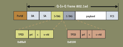
Figure 4. IEEE 802.1ad service and customer tag
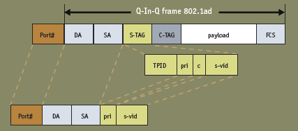
Figure 5. IEEE 802.1ad header extraction
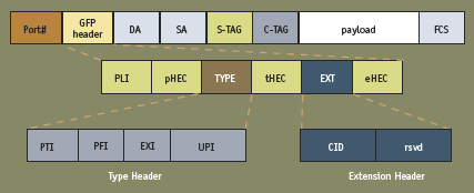
Figure 6. Ethernet 802.1ad over GFP frame format and fields
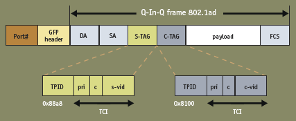
Figure 7. Q-in-Q service and customer tags
Q-in-Q application example
In a Q-in-Q application in a metro Ethernet setting, a VLAN 802.1ad frame (Figure 4), is received in the packet parser. Simple tests can be performed to confirm that the frame is Q-in-Q-compliant. A Q-in-Q frame is characterized by two VLAN tags known as S-TAG (service tag) and C-TAG (customer tag).Within these tags there is a field known as TPID (Tag Protocol ID) which is specified by IEEE 802 for each protocol. Under the Q-in-Q standard, the TPID for C-TAG must equal 0x8100 while the TPID for the S-TAG is 0x88a8. If these values are confirmed in conjunction with the assigned port number (Port#), the packet parser can conclude that it is a Q-in-Q frame.
Once frame type and payload have been identified, it is time to extract some application data and send the parsing results to the classification engine. The actual fields extracted, and hence the action required, depend on the location of a node within the network (i.e., whether it is located at the customer premises, the metro distribution network, or the core transport network).
For example, during Layer-2 Q-in-Q switching in a Metro Ethernet edge switch implementation, the fields of interest for the classifier ACL would include (Figure 5): the destination MAC address (DA), which is used for frame forwarding; the source MAC address (SA), which is used for address learning; the VID in the Service Tag (s-vid), also used for learning and forwarding; and the priority bits in the service tag (pri), which determine how the frame should be queued and scheduled, or in the event of traffic congestion, whether or not the frame can be discarded.
Ethernet-over-GFP application example
Another packet parser design example features an Ethernet 802.1Q VLAN packet that is encapsulated using GFP and transported over a SONET/SDH infrastructure. The example demonstrates the packet parser design flow process step-by-step from the user protocol analysis stage to writing and simulating the packet-parser C-code, leading to the generation and integration of an RTL wrapper ready to load and run the code in the CS90xx device.
Generic framing procedure (GFP – Frame Mode) is an ITU technique used for efficiently and cost effectively encapsulating data packets for transport directly over an underlying SONET/SDH transport circuit. GFP supports a standards-based method to carry Ethernet or PPP/POS (Packet over SONET) traffic – among other protocols – over a kind of infrastructure widely deployed by network and service providers.
To write proper parsing code for the CS90 packet parser, the designer must be familiar with the protocol associated with the user applications to be supported, including the frame format, and especially the frame header fields and the role of each protocol field in supporting the user applications. Figure 6 shows a standard GFP frame transporting Ethernet IEEE 802.1ad VLAN traffic.
GFP itself has a 12 byte header; consisting of the PLI (PDU length indicator) field; the TYPE field; and the EXT (Extension) field. Within the TYPE field, there are other important sub-fields such as the payload type indicator (PTI), which identifies whether the frame is carrying a data or management traffic; the extension header identifier (EXI), which indicates the type of extension header in use; and the user payload identifier (UPI). The UPI identifies the payload mapping in the frame: for example, UPI=1 means the payload is Ethernet while UPI=2 means the payload is PPP/POS. The payload FCS identifier indicates whether the optional GFP FCS at the end of the frame included or not.
The other important GFP header is the optional linear extension header (EXT) which contains the Channel ID (CID) field. The CID is used to multiplex up to 256 different client signals over the same SONET/SDH path, making it ideal for flow classification. For example, each of these client signals may require differentiated QoS treatment (Figure 7). The GFP Header is followed by an Ethernet VLAN Q-in-Q frame consisting of:
- Destination MAC address;
- Source MAC address;
- Tag protocol ID (TPID) for the service tag;
- Tag control information (TCI) for the service tag;
- Tag protocol ID (TPID) for the customer tag; and
- Tag control information (TCI) for the customer tag.
The total size of the GFP and Q-in-Q header to be parsed is 32 bytes, which can easily be accommodated in the 256 byte packet parser cell memory. Note also that a designer may append an optional one-byte port number to identify the physical source port if required for classification.
Analysis and identification of the header field is a necessary first step towards writing code for the packet parser because it provides an indication of the size of the header so space can be allocated for it in the cell memory. But most importantly, the header fields translate directly into the data structures used for manipulating the frame data and extracted selected header fields for packet classification.
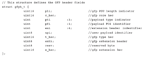
Figure 8. GFP header data structure

Figure 9. Ethernet MAC header data structure

Figure 10. VLAN tag data structure
Data structures
In the Ethernet-over-GFP application example discussed in this note, the data structures derived directly from the frame format are depicted in Figures 8, 9 & 10.
If a parsing solution is to be implemented for a metro edge switch, the requirement would be to strip off the GFP header along with the Service VLAN Tag and route the 802.1Q VLAN frame to its final destination. It may also involve examining the customer VLAN tag in a multipoint service setting. In this case, the parsing process involves the following steps.
The Parser examines the GFP PTI field to determine if the GFP frame is transporting an Ethernet Q-in-Q frame over GFP. This is confirmed by examining the Tag Protocol ID fields. The Service TPID should be 0x88a8 and the Customer TPID should be 0x8100.
After confirming that the payload is Q-in-Q, the parser begins the field extraction process. The fields extracted in this case are also shown in Figure 11 and include:
- The parsing results format (PRF) (for internal signaling);
- Input Port#;
- The payload length indicator (PLI);
- The channel identifier (CID);
- Destination MAC address (DA);
- Source MAC address (SA);
- The priority (PRI) bits associated with the S-TAG;
- The service VLAN ID (S-VID);
- The priority (PRI) bits associated with the C-TAG; and
- The customer VLAN ID (C-VID).
The steps involved in packet parser code development are:
- Parser program coding in C using your favorite text editor;
- Compiling parser code into assembly code using the PPC compiler;
- Simulating parser code using the PPS Simulator;
- Generating machine code and associated data files using PPA assembler;
- Generating the RTL wrapper using cs_macrogen.py utility;
- Inserting parser configuration files in the RTL wrapper; and
- Parser program coding.
The parsing algorithm specified after an analysis of the application protocols to be supported can be implemented using a subset of the ANSI C programming language.While C programming is the preferred programming language because it is simpler and easier to debug, it is also possible to program the parser in assembly language.
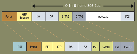
Figure 11. Extracted fields
Conclusion
New network types are converging diverse metropolitan and core transport technologies around a common packet-based optical network infrastructure, bringing together the different services that carriers provide. This integration requires QoS differentiation through flow classification, driving the need for packet handling and processing functions throughout the network.The Packet Parser CPE is one of several embedded configurable blocks included in the CS90 device. These CPEs are designed for maximum performance while maintaining the flexibility that is needed to support the different types of traffic that a given switch or router may see.
Cswitch Corporation
3131 Jay Street, Suite 200
Santa Clara CA 95054
USA
T: +1 408 986 1964
W: www.cswitch.com