Deploying the right tools for mixed signal verification
Engineers on the leading edge of nanometer design are dealing with physical effects that change the way mixed-signal ICs are verified – in timing, power, reliability and yield. With the IC verification effort accounting for 60-80% of the development cycle, choosing and deploying the right mixed-signal verification solution can significantly improve productivity and the return on investment.
Using a system-on-chip (SoC), VoIP over WLAN, design as a case study, this article will describe and compare different verification approaches to identify the nanometer effects in the design, ranging across transistor-level circuit simulation and co-simulation with a digital simulator, as well as the use of mixed-signal behavioral languages.
Choosing the right tools for the job
For this project, the design and verifications teams used a comprehensive list of simulators including SPICE and FastSPICE, Verilog and mixed-signal simulators. Each simulator was dedicated to perform a certain set of verification tasks to ensure an optimized quality of results. For verifying this mixed-signal design, both SPICE and FastSPICE were used extensively.
As IC geometries continue to shrink, the need for an accurate circuit simulator is critical. During the design phase, a highly accurate circuit simulator is required to precisely predict the timing, power consumption, and functionality of designs. SPICE simulators are the most accurate circuit-level simulators. Typically they are used for cell characterization and verification, and the simulation of analog and custom IC designs. The goal of using SPICE is to get the greatest possible accuracy using foundry-certified transistor device models.
For larger block circuit verification, due to the size and complexity of those circuit blocks, SPICE simulators lack both the speed and capacity required. Therefore, the design team for this project relied on using FastSPICE simulators.
FastSPICE is a type of accelerated transistor-level simulator that can use a SPICE netlist directly. FastSPICE deploys a host of techniques targeted to simulate larger designs as fast as possible with user-controlled accuracy. These techniques include circuit partitioning, event-driven simulation, transistor-level model simplification, isomorphic matching, and multi-rate simulation.
During the verification phase, the team faced multiple challenges. The most critical ones were
- IR drop analysis;
- Embedded memory simulation;
- Phase lock loop (PLL) simulation;
- Top-level mixed-signal verification (MSV).
The team used two Synopsys FastSPICE simulators. HSIM was used for IR drop and memory simulation, and NanoSim was used for PLL simulation. Finally, NanoSim and VCS simulators were used for full-chip mixed-signal verification.
IR drop and EM analyses
On an IC, the network between power sources and the core devices is highly resistive. When core devices draw current from the power source, voltage or IR drops appear on the device terminals tied to power nodes. In this example, the supply voltage for the core is only at 1.8V, and any loss of voltage at device terminals can significantly affect the performance of the circuit. In extreme cases, IR drop problems can cause functional failure of the circuit. Furthermore, current flowing through each of the power network branches may cause electro-migration (EM) problems in the circuit if the current density is greater than the threshold specified by the designer’s foundry.

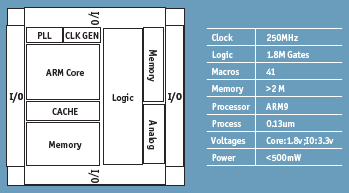
Figure 1. Complex Soc for VoIP over WLAN
The team first evaluated commercial IR drop analysis tools that use a static (vector-less) or ‘pseudo dynamic’ approach. This assumes certain ‘average activity vectors’.
The designers quickly found out that the lack of true dynamic, vector-driven simulation of the entire power network with coupled core devices could result in either overly aggressive or overly pessimistic outcomes.
They decided to use HSIMplus with its Power Net Reliability Analysis (PWRA) option. The HSIMplus PWRA option implements a direct-coupled methodology, enabling designers to determine the impact on circuit timing and functionality caused by dynamic power net voltage drop. In addition to determining the delay degradation induced by voltage drop, PWRA computes detailed time-varying power net voltage drop and current density values, producing information to pin-point power net weaknesses. The analysis results can be directly visualized in a custom layout editor, guiding the designers to real power net problems.
Using HSIMplus with PWRA, the team identified IR drop problems in three separate areas in the memory section of the design. The problems were resolved by adding two extra VDD pads near those areas.
Embedded memory simulation
For the memory sections of this design, the team wanted an effective verification solution to check for functionality, timing, race condition, power and leakage. These memory blocks are too large for conventional SPICE simulators. The need to include extracted interconnect parasitic resistance, and capacitance further complicated this task. For verifying standalone memory, the team used a method for extracting a critical path from the memory design that would allow them to then run SPICE simulation on the much reduced critical path only. However, it should be noted that this technique is not practical for embedded memory applications.
With its hierarchical simulation technology, HSIM can handle large designs with full post-layout data. The isomorphic matching technology in the HSIM simulator takes advantage of any repetitive structures present in the circuit, eliminating unnecessary simulation and accelerating performance. The built-in RC parasitic reduction capability effectively reduces the volume of parasitic data associated with layout parasitic extraction, improving performance for efficient post-layout simulation while maintaining a high level of accuracy.
Since HSIM was able to directly read their SPICE netlist, the designers were able to adapt HSIM to their existing SPICE verification flow. Using HSIM, the team was able to verify all of the memory modules with improved functional coverage in less time.
Simulating PLL – a multi-rate problem
The relative time-step size differences in adjacent circuit blocks have a significant impact on the speed of traditional SPICE simulators. In this design, for example, the PLL has a control loop bandwidth in the kilohertz range, while the VCO runs at 6GHz. In order to simulate the loop response of the PLL, the VCO needs to be run with pS time step, while the loop response time is in the mS range. If SPICE were used, it would result in an extremely long simulation time.
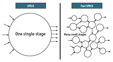
Unlike SPICE simulators that solve the entire circuit as a single large matrix, NanoSim partitions the circuit into many smaller stages. Each stage will be solved as a single matrix, which results in a speed-up in the simulation. Furthermore, the individual circuit that is partitioned can be simulated with a time-based or event-based algorithm. NanoSim runs each partition at its own pace based on its signal frequency, and as a result, NanoSim performs a highly efficient multi-rate simulation.
Using NanoSim, the PLL was simulated accurately in a less than one hour, while the SPICE run time was estimated to take more than 265 hours.
Top-level mixed-signal verification
Top-level verification is an important step before tape-out. Even though each block of the design had been thoroughly validated individually, the team had to put them together and make sure they worked correctly when integrated.

Figure 2. Fast SPICE enables multi-rate simulation
Depending on the type of design, top-level verification is often performed by a FastSPICE simulator such as NanoSim. NanoSim can accept a variety of SPICE and layout-parasitic netlists. It allows users to control the simulation speed and accuracy of the trade-off. When necessary, each circuit block can be ‘tuned’ for better simulation performance while relaxing accuracy requirements.
However, in more complex designs with synthesized logic and third-party intellectual property (IP) modules, a SPICE netlist is often not available for the entire design. Therefore, a viable verification solution must be one that is able to handle not only SPICE, but also RTL, gate, and analog/mixed-signal (AMS) language. Such a solution is often referred to as mixed-signal verification (MSV).
The concept of MSV is well understood. A traditional solution typically links a SPICE simulator to a digital (Verilog or VHDL) simulator. The problem with a SPICE-based solution is that the throughput is severely limited by the SPICE simulator itself. More recent solutions use FastSPICE and a digital simulator to address the needs of top-level verification in larger mixed-signal designs.
For this project, the design verification team was able to deploy NanoSim and VCS simulators for MSV and improve the verification cycle time from over one week (using a SPICE-based solution) to less than five hours. As a direct consequence of running NanoSim and VCS simulators, several critical issues were identified and fixed prior to tape-out. A partial set of those issues was:
- Several DC leakage path and floating gates;
- Bad clock-generation results due to incorrectly connected digital and analog blocks;
- Circuit failed to ‘wake up’ under certain operating conditions due to initialization problems.
To use or not to use Verilog-AMS
For top-level verification, the use of circuit behavioral models written in AMS language can potentially result in better verification performance. However, to create those behavioral modes requires hard-to-find experts in both the circuit-application and modeling-language domains. Furthermore, behavioral models need to be carefully validated against the actual transistor-level designs. Both of those steps can take up a considerable amount of time and expert resources.
Even though NanoSim and VCS simulators are capable of simulating behavioral models written in Verilog-AMS, the team decided against using it for this project. The main reasons were the lack of available expertise and the tight tape-out schedule.
Conclusion
The verification challenges discussed above are by no means unique. As IC fabrication technology and design complexity continue to advance, so will the demand for comprehensive verification solutions for mixed-signal designs. Deploying a robust verification solution will have a direct positive impact on the competitiveness of the product and its overall quality.
Synopsys, Inc.
700 East Middlefield Road
Mountain View,
CA 94043
T: (650) 584-5000 or
(800) 541-7737
www.synopsys.com