Advances in fast-SPICE for mixed-signal SoC verification
Today, most SoC designs include both digital and analog components on the same chip, taking advantage of nanometer geometries. This demands that the current design flow bottleneck due to analog verifi-cation and integration is addressed in ways that enable this process to be completed both thoroughly and efficiently. SPICE simulation was accurate but slow and fast switch-level simulation while being fast, was not quite as accurate. Filling the void is fast-SPICE simulation, with algorithms that provide the right accuracy and performance tradeoffs. Many of today’s fast-SPICE simulators are geared towards either custom logic circuits, or large memory circuit simulations. For today’s complex mixed-signal designs, fast-SPICE simulation can help here but only if the process meets several requirements.
1. The fast-SPICE simulator should be mixed-signal centric for better efficiency.
2. Despite the wide range of circuit topologies in use today, the simulator should be able to deliver accurate results out-of-the-box, and with little or no tuning.
3. The simulator should have the appropriate algorithms to handle low-power applications, especially those required by today’s battery-operated consumer electronics products.
An analog and mixed-signal verification environment that provides the appropriate tools for top-down design and bottom-up verification is necessary for today’s SoC designs.
An IC design today is rarely all-digital. Analog circuitry has become an essential and critical element because of growing demand for functionality that meets the needs of the consumer electronics and automotive markets (e.g. portability, wireless, audio/video, etc.). Nanometer technologies permit levels of integration that were unimaginable even five years ago. Previous process generations enabled the assimilation of several digital components on a single chip, while separate ICs that provided the remaining — primarily analog and mixed-signal (AMS) — functionality were scattered about the system board. The nanometer revolution has enabled the integration of digital and AMS functionality in a single device, as companies have sought to leverage allied benefits such as reduced system assembly cost, lower power, increased speed and reliability, smaller die sizes and so on.
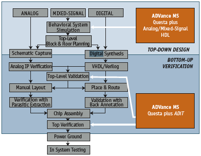
Figure 1. Mixed-signal design flow showing various stages of design and verification
But while more and more designs now have analog components within them, it is still the case that roughly two-thirds of these predominantly digital IC and ASIC designs fail on first silicon. And almost half of these failures have at least one flaw attributable to analog circuit tuning or the mixed-signal interface between the analog and digital blocks. With the respin cost for a deep submicron design now above $500,000, ensuring the accurate chip-level verification of a design before tape-out has become a critical cost and schedule issue.
Statistics show that most system-on-chip (SoC) designs fall into the mixed-signal category, but their verification is far from easy. This is because the design flows and methodologies for digital and analog circuitry are inherently different. The digital flow is usually language-driven and top-down in nature, but the analog flow tends to be more schematic-driven and bottom-up (Figure 1). Nevertheless, to be consistently successful, we need a harmonized mixed-signal methodology that can collaborate with the existing digital and analog flows.
This article considers some of the primary challenges that need to be addressed in reaching this goal, with particular regard to verification and simulation.
Verification and simulation requirements
This harmonized mixed-signal methodology requires a robust verification environment with several indispensable qualities.
It should:
- support AMS HDL languages such as Verilog-AMS and VHDL-AMS (these help extend the well-established language-based top-down digital methodology to the analog world);
- present a user interface that is fully integrated with other EDA company’s analog design environments;
- feature standalone SPICE netlist support;
- include a mixed-signal library of reusable telecommunications blocks making it easy to simulate abstract designs and create accurate models of analog blocks (Figure 2). The TCL scripting language facilitates batch control of simulations.
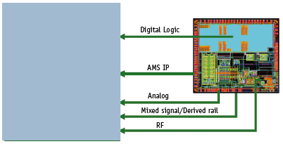
Figure 2. A complete verification environment for analog-mixed signal design
How the simulator is then architected plays an important role in determining its performance and efficiency. A single-kernel architecture allows for a single-netlist hierarchy, no repartitioning of design data, and automatic D/A and A/D converter insertion.
Also, as well as providing superior performance and progressive adaptation to emerging SoC design styles, a single-kernel architecture allows for tight integration with existing RF technology at the transistor level. Within this framework, efficient mixed-signal simulation algorithms then enable bottom-up verification of mixed analog and digital circuits. Furthermore, a top-down design and bottom-up verification methodology can now be used on mixed-signal SoC projects to reduce the risk of respins and accelerate time-to-market.
Many digital-centric designers use Verilog or VHDL to simulate their designs. These designers must increasingly deal with rising analog content and its related impact on circuit behavior. Here, they face a lack of sufficiently accurate methods of modeling and simulating these analog circuits. In this regard, a design and verification system such as Mentor’s ADVance MS, adds a natural AMS extension to existing approaches. It allows designers to use netlists, testbenches, and simulation and debug environments with which they are already familiar. It provides automatic A/D, D/A and I/O port support, together with analog tunneling and digital tunneling. And for circuits with a large analog content, designers can integrate the ADVance MS environment with Mentor’s Mach products. Support also exists for both pre-layout and post-layout verification.
Exploiting fast-SPICE
During the bottom-up verification phase of a mixed-signal design cycle, the capacity and performance of analog simulators represent a major bottleneck. By this point in the design flow, most analog circuits have been realized in a transistor-level representation, and the volume of transistors this encompasses today is often too great for a traditional SPICE simulator to handle. However, the availability of well-integrated fast-SPICE technology in the mixed-signal simulator can relieve this constraint and enable bottom-up verification.
Fast-SPICE underpins a transistor-level simulation technology that first became popular about 10 years ago. It filled the vacuum between accurate SPICE simulation and fast switch-level simulation. With SPICE, circuit devices are modeled by accurate physical equations that satisfy Kirchhoff ’s Law, while switch-level simulators treat each MOS transistor as a simple on/off switch. However, as semiconductor circuits have become larger and more complex, neither SPICE nor switch-level simulators have typically been able to service them because both have encountered shortfalls in performance and/or accuracy. Fast-SPICE technology and its accompanying set of algorithms have enabled effective accuracy and performance trade-offs, greatly accelerating the validation of advanced semiconductor circuits.
To date, there have been two prevalent fast-SPICE technologies.
- The first is based on a switch-level event-driven algorithm, with enhanced accuracy from more accurate PWL-based MOS transistor modeling. Examples of these simulators include Timemill/Powermill (which later became Nanosim) and Mentor Graphics Mach TA. With more accurate modeling for circuit non-linearity, the event-driven based fast-SPICE technology offers much improved timing and power analysis for high performance custom digital circuits.
- The second is based on the SPICE time-point driven algorithm, with added circuit partitioning technology and simplified transistor modeling for improved performance. Examples of these simulators are Starsim (formerly ADM) and Hsim. Time-point driven fast-SPICE has greatly improved performance, and has reasonable accuracy, being most appropriate for large memory and lengthy mixed-signal circuit simulations.
All commercial fast-SPICE simulators claim that they can be fast and accurate for all transistor-level circuits, but the reality is that, according to their fundamentally different algorithms, each is stronger in some applications and weaker in others.
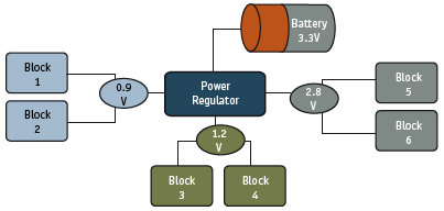
Figure 3. Derived rail algorithm for non-ideal power designs
For example, Nanosim inherited its Timemill/Powermill event-driven architecture, and therefore was fast for custom logic circuits but perhaps not sufficiently accurate or user-friendly for memory or mixed-signal circuits. Meanwhile, Hsim uses hierarchical simulation technology and is most valuable for large memory circuit simulations. However, it may not be as efficient or accurate for mixed-signal projects, where circuits are usually smaller and the circuit hierarchy is not repetitive.
Indeed, hitherto, no fast-SPICE technology specialized in mixed-signal circuits. These circuits are usually much smaller than both custom logic and memory circuits, and demand much higher accuracy as well as the ability to deal with greater circuit complexity. However, a fast-SPICE simulation technology has now been developed and optimized specifically for mixed-signal applications, such as PLL, DLL, DAC, ADC, LDO, and SERDES.
This new variant is based on the time-point driven SPICE algorithm, and in addition to circuit partitioning and table modeling techniques, it also implements many unique mixed-signal-aware algorithms to ensure the correct and accurate simulation of complicated and demanding circuits such as those noted directly above. To do this, such a dedicated technology needs — and has — a collection of mixedsignal-aware algorithms, such as mixed-signal-aware partitioning, charge-conservation, and non-ideal power-supply support. The combination offers the best accuracy and performance trade-offs for mixed-signal applications, and this is especially true for circuits that operate with non-ideal power supplies.
There is growing demand for consumer electronic goods with efficient battery operation such as cellular phones, portable game consoles, and music players. Conventional fast-SPICE simulators use DC-connected partitioning. Here, all nodes in the same DC path are grouped together. Ideal VDD and VSS signals enable the DC-connected partitions to be isolated, and hence they can be solved individually. However, for today’s battery-powered designs, the VDD and VSS are usually regulated with an internal power supply (Figure 3). This implies that the VDD/VSS signals are no longer ideal, and for this reason, many existing fast-SPICE simulators handle derived rail designs poorly. By contrast, the new generation of fast-SPICE simulators has proven derived rail algorithms that enable the fast and accurate simulation of non-ideal power designs.
Mixed-signal circuits employ a wide variety of circuit topologies and design techniques and these also present great challenges to traditional fast-SPICE simulators. In some cases, the user must activate non-standard options so that the simulation algorithm is correctly tuned; otherwise, the simulation will not deliver reasonable results. The process of finding which options are necessary is tedious and can take days to complete. A system that has the right mix of mixed-signal-aware algorithms can produce accurate results without the need for such tuning, or only a minimal amount. This has obvious productivity benefits for the overall verification process.
The need for out-of-the-box fast-SPICE accuracy is greater still when the circuit under validation is driven by testbenches for analog cell characterization or by digital automatic testbenches, such as SystemVerilog. Here, testbenches and input excitations are configured dynamically, making a customized option setting for each design impossible. The best solutions available to the AMS designer, such as Mentor’s ADiT, integrate fast-SPICE technology into an existing and competent AMS verification flow. This provides the optimal platform for bottom-up verification of mixed-signal SoCs. The greater capacity and higher performance of the fast-SPICE simulator allows large transistor-level analog circuits to be included in the mixed-signal simulation.
In short, the high stability and accuracy available with dedicated AMS fast-SPICE in an integrated tools environment ensure excellent ease-of-use, high confidence in simulation results and improved design cycle times. With the addition of this new fast-SPICE technology, an AMS design flow can truly support top-down design and bottom-up verification for advanced mixed-signal SoCs with the highest functionality, capacity, performance, and most of all, accuracy.
Mentor Graphics
Corporate Office
8005 SW Boeckman Rd
Wilsonville OR 97070
USA
T: +1 800 547 3000
W: http://www.mentor.com/supportnet