A verification methodology for programmable and reconfigurable processors
The article describes and illustrates, by way of a case study, an innovative approach to functional verification. It enables the reuse of test patterns through the coordinated combination of a top-level testbench and subordinate testbench modules. It is based on a new add-on tool, VTrac+, that extends Mentor Graphics’ ModelSim/Questa software to stimulate, compare and trace signals. The add-on is used for pattern transfer inside hierarchical testbenches; the automated evaluation of hundreds of thousands of patterns in regression test suites; and the injection of test patterns generated by third-party tools.
The increasing complexity of digital designs for communications applications is raising the demands placed upon verification strategies. Functional and formal verification methods are used and, increasingly, combined to realize methodologies that address the growing functionality of the silicon. Next generation communications ICs are characterized by:
- flexible, programmable architectures that support multiple mobile radio andWLAN standards;
- on-chip processors for filter operations, channel encoding and decoding;
- and the clustering of single instruction multiple data (SIMD) DSP cores.
Figure 1 shows key parts of the structure of an innovative programmable processor. All the components are connected by a central multi-layer bus and can access shared memory. The main data processing activity takes place in a cluster of four SIMD cores. Every SIMD core processes several parallel tasks, each controlled by a general purpose core. The main verification challenges for such systems are:
- test of hardware-software communication;
- test of the hardware with real data processing algorithms;
- test for deadlocks in a parallel architecture;
- test of shared memory access via the system bus;
- measurement of data throughput;
- and proof of the logical correctness, given the time conditions (clock exact).
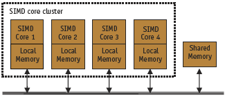
Figure 1. Part of a multi processor architecture
Verification environment
Figure 2 shows our synthesis and verification flow in graphical (Figure 2A) and tabular (Figure 2B) forms. The classical synthesis environment uses commercial tools from Mentor Graphics and Synopsys for schematic entry, HDL simulation and synthesis. Additional tools are used for system design and reference simulation.
In the verification environment, we combine in-house tools with commercial solutions. Coding style and design rules are first checked using our in-house Regatta tool. Then, tools from OneSpin Solutions are used for formal verification. All units of a design are subjected to formal verification under intent and equivalence check. Based on properties derived from the specification, a model check is performed for selected modules.We recommend using a formal model check for blocks, preferably with a high percentage of combinational logic and/or complex state machines. Otherwise, such blocks require so many test patterns that the simulation becomes extremely lengthy.
To bridge the gap between formal and functional verification methods, we favor assertion-based verification using SystemVerilog Assertions within Questa. Extensive functional verification is done using the capabilities of Questa for constraint random verification, code coverage and functional coverage. Additionally, we enhance our functional coverage significantly by using an in-house tool, VTrac+.
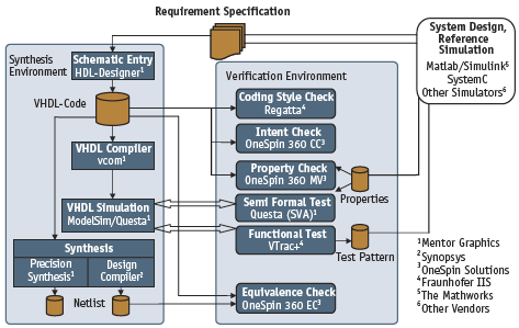
Figure 2a. Synthesis and verification environment (graphical)
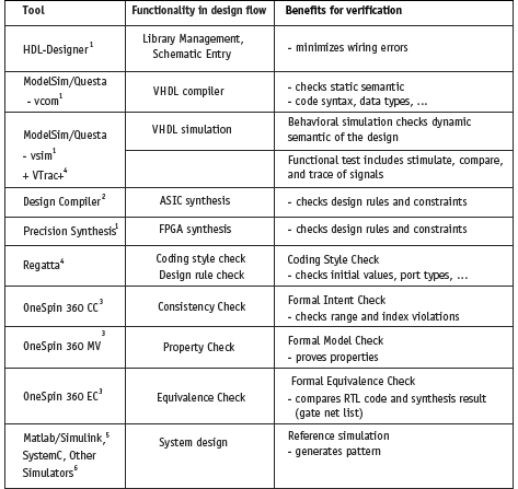
Figure 2b.Synthesis and verification environment (tabular)
Reference simulation
A useful technique for the verification of dedicated functionality in programmable processors is to run parts of real data processing algorithms on the VHDL model of the SIMD core. Test scenario examples include the transfer of memory contents and the manipulation of semaphores. The behavior of the design in error scenarios can be examined by, for example, the incorrect initialization of memory and semaphores, and randomly blocked memory accesses. A processor reference model provides an efficient way of generating test patterns that cover the specified functional range. In our methodology, an adapted instruction-set simulator is employed. Programs for the SIMD core are tested using this reference simulator, and it is enhanced with output routines for logging instruction sequences and memory contents into files.
Logging is triggered before and after data processing (Figure 3, p.26). The logfiles are used as stimuli and references for the VHDL simulation. Thus, data and instructions in amicro programform the test pattern for a VHDL simulation. Integration of the pattern into the simulation is achieved by file I/O with testbench components.
Response comparison is done during VHDL simulation by special VHDL testbench components, and after simulation by Perl scripts. Some disadvantages with VHDL testbench components are a relatively high implementation effort and restricted access to signals only in the local design hierarchy level.
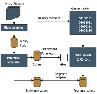
Figure 3. Reference simulation
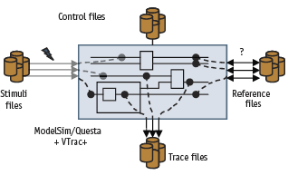
Figure 4. Pattern integration using VTrac+
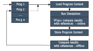
Figure 5. Regression test sequence
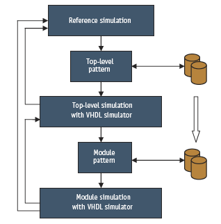
Figure 6. Pattern transfer in a hierarchical test-bench
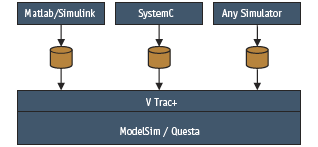
Figure 7. Pattern integration from external tools
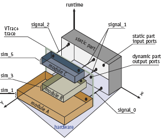
Figure 8. Trace mode of VTrac+
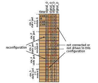
Figure 9. Trace file of VTrac+
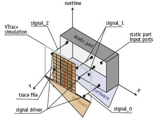
Figure 10. Simulation mode of VTrac+
VTrac+
A better solution to the integration of test patterns into VHDL simulations is offered by the in-house tool VTrac+ (Verification Trace and More). It is an add-on tool for ModelSim/Questa and is linked over the Foreign Language Interface (FLI) to the simulator (Figure 4, p.26).
The tool creates an efficient link between signals in any design hierarchy and corresponding values (patterns) in formatted ASCII files. The relationship between the signals in the design and the patterns in a so-called ‘pattern file’ is established by a ‘control file’. In the control file, the name of the associated pattern file, the list of signal names, and the operation mode of VTrac+ must be stated. The tool is instantiable up to 1,000 instances, and every instance uses a pair of files. The number of signals per instance is unlimited. Inside the VHDL code, the tool is called like a common VHDL procedure. Thus, the designer defines the trigger time for calling VTrac+.
VTrac+ has three main modes.
- Trace signal values into pattern files. At each specific trigger (e.g., the rising edge of the clock), it dumps the values of the signals defined in the control file into the pattern file (trace file).
- Compare signal values in design and pattern files. At each trigger, it compares the signal values in the current simulation with expected signal values read from a line of the pattern file.
- Stimulate signal values. At each trigger, VTrac+ reads a line of the pattern file and sets the corresponding signal in the design to this value.
We have found that using this tool is the simplest way to integrate a very large volume of test patterns. It supports nearly all scalar and compound VHDL data types.
VTrac+ use cases
VTrac+ enables many aspects of functional verification. In our verification environment, for example, it is used for:
- the automatic comparison of patterns in regression test suites;
- pattern transfer in hierarchical test-benches;
- pattern integration from third-party tools;
- and partial dynamic reconfiguration.
Regression test
Each design change requires the repetition of all tests, even those successfully completed for earlier versions of the model.We automate these regression tests using TCL scripting within ModelSim/Questa.Various micro programs are executed consecutively on the VHDL model of the core. TheModelSim/Questa GUI is enhanced with popup windows enabling the designer to run a program by simply pushing a button. Each run includes a loading phase, the simulation run, a results store process, and a compare phase checking the results (Figure 5).
The simulation results are compared to the references for contents of shared and local memory; access sequences to local memory; and contents of processor-internal status registers. The results are annotated as ‘ok’ or ‘not ok’ in the GUI. Additionally, VTrac+ compares specific online signals with values that were recorded before the design changed.
Hierarchical testbenches
Complex circuits are usually designed by several engineers who work on modules and test them on a standalone basis. At the top level, the modules are used as black boxes and their interactions are tested. During top-level simulation, errors in a specific module are hard to locate.Module designers often cannot provoke failure scenarios similar to the test environment of the top-level simulation. The problem is that some errors cannot be reproduced. One solution is to use hierarchical testbenches, whereby system patterns on the module level are reused.
The concept uses a top-level testbench with subordinated module testbenches. This approach requires clearly defined module entities and an efficient pattern transfer technology. To this end, VTrac+ traces the interface signals of the modules at the top level and stimulates these into module testbenches (Figure 6). Thus, the module test runs the same scenario as the top-level testbench.
Pattern integration
Design and verification environments usually include several external tools on the periphery of a HDL simulator. For example, Matlab/Simulink and SystemC are often used for system design, performance checks, and reference simulation. Patterns generated by external tools must also be integrated into the HDL simulation (Figure 7).
We have used VTrac+ to integrate hundreds of thousands of patterns generated by Matlab/Simulink. These were printed out during a Matlab/Simulink simulation using standard I/O routines and applied as stimuli into the subsequent VHDL simulation by VTrac+. If the external tool cannot generate the pattern in the VTrac+ file format, a conversion step is necessary.
Other applications
VTrac+ can be used for the simulation of reconfigurable hardware. The ability to adapt hardware parameters during the runtime simplifies the processing of new components and accelerates the implementation of new standards. Such systems can be revised without downtime or the loss of synchronization.
Current hardware simulators cannot simulate a partial dynamic reconfigurable design. Switching off or exchanging hardware during the simulation entails restarting the simulator. This section describes the simulation of a partial run-time reconfigurable (pRTR) design by the connection of several simulations.
The technique is based on partitioning the pRTR design into separate executable parts. During the separate enclosed simulations, the approach scans and stores selective signals and generates a complete simulation from them. The emphasis lies in the simulator coupling and simultaneous tracing of relevant signals.
Figure 8 depicts the time distribution of a pRTR design consisting of one static and three dynamic parts. The static part is active during the entire runtime. The dynamic parts are reconfigured after a reconfiguration time.
VTrac+ traces the signals driven from the dynamic parts during the several simulations. The logical expressions of the signals are then stored in a trace file (Figure 9, p.27). The tool works at a rate of two samples per clock period.
The assembly phase starts when the signal traces in all simulations are complete. Here, the original HDL architectures of the dynamic components are replaced by VTrac+ instances that now simulate the out-ports of the dynamic modules over the simulation time (Figure 10). Thereby, an assembly of different simulation runs is possible. Using a schedule of the simulations, simulation of an entire pRTR-system is possible.
In the wave diagram in Figure 11, an example of the hardware exchange during run-time is depicted. An adder is substituted by a multiplier after a reconfiguration time. During the reconfiguration, the signal connected to the out-port of the module (mic21_z_i) is not driven.
Conclusions
We have described a design and verification environment that combines tools for formal and functional verification. Formal verification increases design reliability and cuts the simulation effort significantly. Functional verification of programmable controllers requires dedicated tests of the design, too.We use a reference simulator for generating stimuli and responses, and inject these patterns into a VHDL testbench. Thus, we can run parts of real micro programs on the VHDL model of the design. The VTrac+ add-on tool has proved an efficient source for the pattern integration of third party tools into HDL simulations by ModelSim/Questa. Test effectiveness has greatly increased, especially for automatic pattern comparison during regression test and design stimulation.
The presented hierarchical testbench concept is based on a top-level testbench with subordinated module testbenches, and on VTrac+. The top-level testbench is used for verification at the system level and also to generate patterns that can be reused as stimuli in the module testbenches. Each module testbench works for subordinate blocks in a manner similar to the toplevel testbench.
Assertion-based verification methods will, in future, bridge the gap between formal and functional verification. In this context, the capabilities of VTrac+ will be enhanced by an implementation under the Verilog Procedural Interface.
Common simulators may be connected by VTrac+. Thereby, the assembly of several simulation runs is possible. This is the essential precondition to represent the behavior of a pRTR-system. Furthermore, assembling multiple FPGA platforms with a common simulator is possible using VTrac+.
Fraunhofer Institute for Integrated Circuits
Design Automation Division
Dresden
Germany
T: +49 (0)351 4640 701
W: www.eas.iis.fraunhofer.de