A SystemVerilog AMBA ABP monitor
Productivity levels for hardware design, specification, simulation and validation have been raised by the formal approval of IEEE 1800 SystemVerilog as an industry standard. Evolved from the Verilog hardware description language, SystemVerilog is now the language of choice for developing verification and design intellectual property (IP). As a result, EDA companies are progressing rapidly in delivering support for it.
The language’s advanced design modeling capabilities support the design of large gate-count, IP-based bus-intensive chips. SystemVerilog also provides support for testbench capabilities such as randomization and coverage.
A crucial part of the SystemVerilog language is assertions. By adopting an assertion-based verification (ABV) methodology, existing verification flows can be improved. Indeed, assertion-based design and verification is an absolute necessity in today’s large, complex designs, and the use of assertions can equally apply to the simplest projects.
Choosing the verification environment
Simply adopting the SystemVerilog standard will not guarantee the successful completion of design and verification. Design teams must completely understand the requirements for the product being developed, and all these features must be well-defined so that a comprehensive test plan can be put in place by the verification team.
Correctness and completeness determination, virtual devices that stimulate interesting situations, and devices that accurately collect and analyze data are all vital to the creation of a comprehensive verification environment.
The overall objective is to write the least code necessary to create all the facilities that adequately verify the design. The less code the verification engineers write the better because this means there is less code to debug, test, maintain, and document. Also, it enables the design of testbench architectures that are themselves easy to build, debug, maintain, and understand.
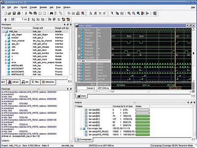
Figure 1. Questa GUI
This article will discuss work undertaken by HDL Design House in the context of Questa, Mentor Graphics’ advanced verification environment. It is a standards-based simulator that supports SystemVerilog in a single, native kernel with an advanced constraint solver enabling the automatic creation of complex input stimulus combinations. Questa supports verification methodologies such as testbench automation, coverage-driven verification (CDV), ABV and transaction level modeling (TLM). It has also inherited a powerful, intuitive GUI from ModelSim that makes the analysis process very easy (Figure 1). Questa enables the use of a complete set of advanced verification methodologies because of its flexible architecture and its native support for SystemVerilog, PSL, SystemC, Verilog, and VHDL.
ABV makes assertions a key element of verification because it ensures that fundamental design properties cannot be violated or overlooked. Assertions can be configured so that
- Failure and pass tracking can be enabled or disabled;
- The severity level at which an immediate assertion will cause a simulation break can be set;
- The assertions failure action can be set;
- Weights can be assigned to cover directives.
SystemVerilog-constrained random verification features allow for the automatic creation of complex input stimulus combinations that are difficult to create manually. Stimulus scenarios can be described in terms of constraints. SystemVerilog follows an object-oriented paradigm. In addition the constraints mechanism has been built cleanly on top of SystemVerilog. Through an object-oriented technique called ‘inheritance’, different constraints – and therefore different scenarios – can be built. These constrained random features simplify reuse at the testbench level, thereby reducing the number of testbenches that need to be written while increasing the number of tests generated.
With its comprehensive support for assertions, interfaces, classes, constrained randomization and random sequence and stream generation, QuestaSim is a good environment for SystemVerilog integrated design and verification approach.
Adopting the methodology
Testbenches usually perform the following core functions, and verification engineers typically need to develop separate routines for each one:
- Generate stimulus (either random or directed);
- Convert the stimulus into pin activity for the design under test (DUT);
- Monitor output interfaces and intercept interesting responses;
- Compare responses with some references;
- Count the various kinds of response (ie. collect coverage information);
- Control stimulus generation based on coverage.
SystemVerilog assertions (SVAs) increase how much can be observed for each function they represent. The possibility of binding assertions to design structures enables the independent and separate development of assertions from that for design code.
SVAs can describe very sophisticated sequences of signal changes in a short and precise manner, specifying the expected results or flagging deviations. Questa has a built-in SVA assertion browser and this helps the user to debug assertions effectively and identify the event that caused an assertion to fail, directly tracing the violated signal back to the source code.
Beside support of SystemVerilog and all standard HDLs for design and verification, Questa promotes the adoption of the Mentor Graphics Advanced Verification Methodology (AVM). This provides a way to organize and build verification infrastructures by following established principles. AVM describes a TLM based verification methodology that promotes modularity and reusability. Based on a leveraging of well-defined TLM interfaces, it allows the design to be verified at the various levels of abstraction from system level to gates.
Case study: AMBA APB SystemVerilog Monitor
This section offers a brief overview of the development of an SVA monitor checker that was developed by using AVM as the driving methodology.
A testbench that follows AVM principles has to be organized in concentric rings, where the innermost ‘ring’ is the DUT, followed by transactors, reference models, generators, and finally, collectors and test controllers.
HVC_710_SV is an SVA monitor/checker for the AMBA APB protocol that has been developed by HDL. It is compliant with the ARM AMBA APB3 protocol specification [4]. As it is also fully compliant with the SystemVerilog specification and Mentor’s AVM methodology, it is a verification building block that provides modularity, data hiding, layering and reuse in AVM-based tesbenches.
HVC_710_SV is highly suitable for the development and debug of APB-based modules or the integration of designs that are based on AMBA APB as core interconnect. A passive component monitor performs two functions: it checks protocol and detects APB transactions, and then makes them available to the rest of testbench.
Figure 2. APB Monitor in testbench environment
The block diagram in Figure 2 shows a usage flow for a hdh_apb_monitor.
Blocks that are part of the testbench example are very easily instantiated one-by-one in the top file. Well- defined interfaces for connecting components are key enablers for achieving modularity and reuse. It is not necessary to understand the substance of the component implementation in the interface; it is only important that it conforms to the interface. The same is true for the transaction-level models and verification components, but at a more abstract level. The APB interface module is parameterizable with data and address bus width. Adequate modports are defined for the monitor, driver, and slave.
hdh_apb_if #(.AWIDTH(ADDRWIDTH),
// address width – up to 32 bits
.DWIDTH(DATAWIDTH)
// data width – up to 32 bits
) mst2slv(apb_clk, apb_rst);
As mentioned above, SVAs are good for checking that design protocols meet specification, e.g. checking one of the properties for APB bus transactions – the setup phase. They also allow this sort of check to be deployed during simulation, or proved using formal model checking tools.
property p_setup_phase_enable_check(resetting);
@(posedge pins.PCLK)
disable iff (resetting) (|pins.PSEL & !pins.PENABLE) |=> pins.PENABLE;
endproperty : p_setup_phase_enable_check
There are 15 APB protocol checks implemented in HVC_710_SV as SVA assertions. According to APB functionality, they are grouped:
- Signal testing;
- Signal retraction testing;
- Phase-based testing;
- Low power retraction;
- Other checks.
The data and control signals in the testbench and DUT can be classified into two types: ‘in-band’ and ‘out-of-band’. In-band data is that which is involved with the functioning of the DUT (data from stimulus generators, signals flowing through the DUT and results data captured on its outputs). Out-of-band data is involved with the functioning of the testbench (signals to control the testbench, configuration data, analyzed data, coverage etc.).
The transaction operations are also provided in two flavors: ‘blocking’ and ‘nonblocking’. In a blocking transaction, the initiator will wait for the transaction to complete. A nonblocking transaction will return immediately. A nonblocking transaction may still take some time to complete, but the initiator will meanwhile be free to react to other activity.
Transactions are communicated between an initiator (e.g. a stimulus generator) and a target (driver). Stream of transactions are then processed by a target (driver) and applied to a bus.
Initiator – transaction level stimulus: a random constrained transaction level stimulus generator
hdh_apb_stimulus stim(
.comm(trans_channel)
);
Target – pin level driver: a simple driver for generating a transaction on the bus
hdh_apb_driver apb_drv(.pins(mst2slv),
.xport(trans_channel)
);
Communication between initiator and target is done via FIFO TLM for requests and response queuing, according to the AVM.
tlm_req_rsp_channel #(
.REQ(apb_req_t),
.RSP(apb_rsp_t),
.BOUND(1) // configurable depth of fifo in transport channel
) trans_channel();
In TLM, it is necessary to have insight into the transaction stream to communicate the traffic to other devices. In verification environments, this type of device is called a monitor. A monitor, in most cases, does not connect to anything other than the bus, and here may simply print out debugging information to a standard output, a log file or a database. On the other hand, it can also supply transaction-level information about the bus traffic to one or more of the components connected to it.
A monitor, actually, converts in-band protocol data (from APB bus) into out-of-band transactions. The monitor watches pin level activity on the bus that connects the driver and DUT (in our case hdh_apb_driver and hdh_apb_slave). The transactions it recognizes are sent out to the analysis port, which is depicted in the diagram as a small box on the top of the monitor. The out-of-band transactions are then available for analyzing (coverage, performance) or to confirm the correct functioning of the DUT. The following example of code shows monitor instantiation in a SystemVerilog testbench developed under the Mentor AVM [2]:
hdh_apb_monitor monitor(mst2slv);
An analysis port is a transaction port with a simple write interface. The write function emits data from the sender, in this case a monitor, to a receiver that may be a coverage collector, scoreboard, or other verification component.
The SystemVerilog implementation of analysis ports uses a publisher/subscriber model. Subscribers connect to the publisher and when the publisher has some new data to publish it passes the data to each subscriber. To use an analysis port the sender just needs to instantiate the analysis_port interface and call write() to send something to the receiver. It is necessary also to supply a type for parameter T that defines the type of object travelling between the sender and receiver(s).
analysis_port #(
.T(apb_xact_t)
) xact_analysis();
Analysis ports are depicted in Figure 2 as small boxes on the top and on the left of the monitor:
- err_analysis
Error analysis is actually done in the monitor. With respect to the Mentor AVM, the Error Analysis block gains available access to the Monitor via this port. The Error Analysis block can further process information at the transaction level (for example, the test controller can have access to the Error Analysis block, and it can stop simulation if an error occurs).
- xact_analysis
The Scoreboard and Coverage Collector blocks collect information via this port from the Monitor at transaction level.
Conclusion
HDL Design House has been very active in adopting SystemVerilog and its methodologies as a unified approach for our current and upcoming design projects. It makes it much easier to transcend the gap between increasing design complexity and customer demands for reduced time to market.
An inherent objective for the HVC_710_SV monitor in raising the level of abstraction and moving out of the signal level domain into the transaction level domain is attained. The example shown above implements TLM in SystemVerilog and a methodology based on Mentor’s AVM, consistent with with SystemVerilog AVM based solutions. SystemVerilog verification solutions for other standard interfaces – AMBA AHB, I2C, SATA – have also been developed.
References:
- Accelera, SystemVerilog 3.1a Language Reference Manual, 2004, http://www.accelera.org
- “Verification Cookbook: Advanced Verification Methodology (SystemC and SystemVerilog), V1.2”, Mentor Graphics® Corporation, October 28, 2005, http://www.mentor.com
- B.Cohen, S.Venkataramanan and A.Kumari, “SystemVerilog Assertions Handbook …for formal and dynamic Verification”, VhdlCohen Publishing, 2005, http://www.vhdlcohen.com
- AMBA 3 APB Protocol Specification (v1.0), 2004, ARM IHI 0024B, http://www.arm.com
HDL Design House,
Makenzijeva 79/III
11000 Belgrade
Serbia and Montenegro
www.hdl-dh.com
T : +381 (0)11 245 7998
F : +381 (0)11 245-9987