Make best-practice lean NPI for PCB a reality
Almost every PCB designer has had problems when a product has gone to manufacturing. They are often associated with manufacturing processes or yields, or with PCB assembly, and result in scrap or a lot of rework. When they occurs, modifications become necessary and the product is re-spun at the design level until a satisfactory match with the intended manufacturing process is achieved.
This is not so surprising, given the laborious steps in a traditional design-to-manufacture process.
First, the designer sends separate bills-of-materials (BOMs), Gerber files, component position lists, drawings, netlists, and other data in various forms and formats.
Assembly, test, and production engineers take these go through many steps to recompile and rebuild a product model before process-level new product introduction (NPI) can begin.
Next, the BOM and a set of assembly drawings (such as a mechanical drawing of an assembly panel showing the step-and-repeat configuration and all the dimensions necessary to define the panel) are sent to the fabricators. These contain the specifications and requirements needed by the manufacturer to deliver the correct product.
A fabricator then recreates the drawing in a CAM system which is sent back to the designer for approval. And there could still be several further iterations before the designer approves the drawing as ready for fabrication, particularly if errors are found on it.
This is time-consuming and inefficient design.
The benefits of ‘lean NPI’
A better approach is to adopt a lean NPI methodology for design-for-manufacture (DFM). A lean NPI methodology begins in the design organization with DFM analysis and optimization feedback. It includes creation of the manufacturing-level product model, including design and verification of the assembly panel. From that master manufacturing product-model, the manufacturing-process data can then be automatically generated for fabrication, assembly, and test.
A lean NPI workflow includes a ‘product’ and a ‘process’ phase. The product phase defines exactly what is to be manufactured. The process phase defines how the product will be manufactured. Efficient hand-off between product- and process-phases of NPI can be achieved by using an ODB++ product model. ODB++ is an intelligent and open single-data structure for transferring PCB designs into fabrication, assembly and test. A well-constructed ODB++ product model replaces multiple traditional data files and drawings, and this allows for an automatic transition between the product and process disciplines.
For every new PCB-based product, you can now easily and efficiently link the design phase, where you determine the functionality and physical model of the product and how it will look when assembled, to the process phase that defines how the product is going to be manufactured and what fabrication processes need to be used.
Using a dedicated DFM analysis tool during PCB design ensures that the result complies with the manufacturer’s capabilities and also that it does not cause any problems because of the conflicts with constraints imposed by the manufacturing processes. The rules used for DFM analysis derive directly from the manufacturers’ constraints and their capabilities.
Holding regular review meetings with the manufacturer ensures that the DFM rules used at the design level are always up to date with process capabilities. Thus, costly and time-consuming problems experienced during fabrication can be avoided. Moreover, areas where the design can be improved can be identified to ensure maximum yield.
Catching DFM problems early during PCB design saves time because fixes become more difficult to make at later stages. Also in this process, designers become more “manufacturing aware” as they work.
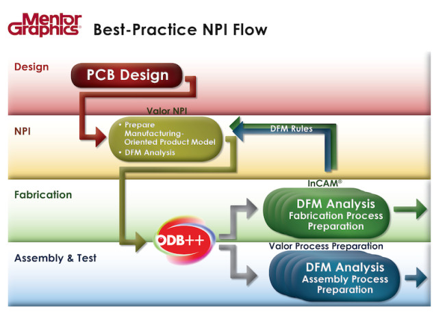
Figure 1 Best practice NPI flow (Source: Mentor Graphics)
Mentor Graphics established the ODB++ data format and has just launched the industry’s first integrated, automated lean NPI flow for the design, fabrication and assembly of PCBs. As the graphic above shows, a best-practice lean NPI flow entails using enhanced, intelligent ODB++ product model data, concurrent DFM during the PCB design, and DFM rules that are derived directly from the manufacturer’s rules and process constraints. Adopting all three of these practices will result in a lean NPI process.
Using Mentor’s integrated PCB design and DFM tools for a lean NPI methodology enables PCB companies to reduce the number of revision spins and leads to fewer manufacturing problems. The benefits from this methodology are reduced time from design-to-volume production with higher manufacturing yields and product reliability, consistent product manufacturing across multiple manufacturers, and reduced development costs and shorter time-to-market schedules.
Further information
Learn more about Mentor Graphics’ strategy for lean NPI on its website.
About the author
Julian Coates is the director of business development for Mentor Graphics’ Valor division. Since joining Valor in 1994, Julian has fulfilled a number of roles including managing director of Valor’s European subsidiary. Prior to Valor, He was the northern European sales manager, and then VP of sales-Europe, for Optrotech SA. From 1979-1986 Julian worked at British Aerospace, holding the positions of mechanical design engineer, PCB production engineer, and production manager. He holds a degree in Engineering Science from Exeter University.
 Julian Coates is the director of business development for Mentor Graphics Valor division.


