Designing an interactive GUI
Consumers want high-end GUIs on portable devices, but most MCUs—even those at 32bit—do not have the capacity to support embedded versions of these on their own.
The article outlines the collaboration between Atmel, which has a family of customizable MCUs, and Amulet Technologies, a specialist in GUIs based on a compressed version of HTML.
It describes features of the two companies’ products that allow both electronics engineers and graphic artists to make their contributions to a project within familiar design environments. It also illustrates many of the options that allow for the customization of the latest generation of ARM7-based MCUs
Largely thanks to Apple’s iPod family, consumers expect visually appealing, easy-to-use and reliable graphical user interfaces (GUIs) on every product they buy. These interactive GUIs are the wave of the future.
Designing an embedded system that responds in real time usually involves a lot of programming. So, while a GUI is normally a graphics design task using languages such as HTML, one intended for an embedded device usually needs to be written by an engineer employing C in conjunction with graphic libraries and other software. The obvious problem: engineers are not graphic designers and graphic designers are not engineers.
In addition, a full-color, interactive GUI requires a real desktop-style operating system (OS) that substantially exceeds the memory addressing capabilities of most 8bit and 16bit processors, and even some 32bit microcontrollers (MCUs). The vast majority of embedded systems have been implemented with 8bit or 16bit MCUs, and no OS or a simple RTOS kernel.
Bridging the gap
The first step toward adding an interactive GUI to an embedded system is probably to migrate to a 32bit MCU. However, an ARM7-based 32bit MCU that meets this kind of design’s cost and power consumption constraints does not have the memory bandwidth to accommodate the display refresh requirements of full-color LCDs. Nor does it have the bandwidth to run a desktop-style OS. On the other hand, 400MHz+ GUI-capable processors consume too much power and cost too much for many embedded applications.
Also, most embedded GUIs require so large a frame buffer memory that it is not cost-effective to put the buffer on the MCU. A 24bit color VGA (640x480pi) LCD requires a buffer of 1.2Mbytes. An MCU with this much internal SRAM would be prohibitively expensive, so the frame buffer must be stored in external RAM. The minimum refresh rate for an LCD is typically 60 frames per second. This means that the CPU needs to fetch 73Mb/s. Even at 80MHz, a conventional and affordable ARM7 processor cannot achieve this throughput.
One option is a third-party GUI OS, such as that provided by Amulet Technologies. It was designed to allow the graphic portion of the design to be partitioned from the embedded control part of the application, easing collaboration between embedded engineers and graphic designers. Using Amulet’s tool chain and GUI OS, the look and feel of the GUI is authored by graphic designers and usability experts using HTML and graphics authoring tools. The GUI OS then generates parametric data that gives the embedded engineer control and easy access to the GUI from the C-code. Art directors need not become C gurus; embedded engineers need not become HTML mavens.
Partitioning the design in this way also simplifies test. The embedded device can be tested independently of the GUI by manipulating the same variables that would otherwise come from the GUI. Likewise, user-testing of the GUI can be conducted in parallel with the development of the embedded control code. More importantly, embedded programmers no longer need to worry about last minute GUI changes breaking the control system code.
Implementation
Implementing a design that is partitioned between the silicon GUI OS and an ARM7 MCU would typically require a custom ASIC. Unfortunately, custom ASICs take a year or more to develop, cost a fortune to design, have minimum orders in the hundreds of thousands of units and provide little chance to test market and refine the design. They are beyond all but a handful of consumer product companies. These dynamics led Amulet to port its technology to an ARM7-based customizable MCU from Atmel, licensing its technology as hard IP embedded in the chip.
Atmel’s CAP customizable MCUs are standard product ARM7- or ARM9-based devices with a multi-layer bus, peripheral direct memory access (DMA) controller, external bus interface (EBI), USB, serial peripheral interface (SPI), two wire interface (TWI) and other peripherals, plus a metal programmable (MP) block that can be used to implement coprocessors, DSP algorithms, or custom peripheral sets (Figure 1).
Source: Atmel
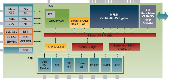
FIGURE 1 CAP7 block diagram
The MP block
The MP block (Figure 2, p.24) on the CAP7 has the equivalent of 28K or 50K FPGA LUTs (250K or 450K routable ASIC gates). It also has a number of internal features and dedicated external connections to ease the implementation of application-specific logic. Internally, it has two 2Kx16 dual-port RAM blocks that can be tightly coupled to the logic elements that require them.
Source: Atmel
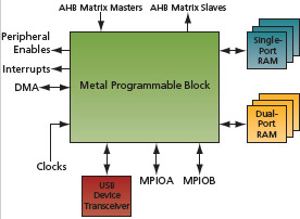
FIGURE 2 MP block interfaces
Source: Amulet Technologies
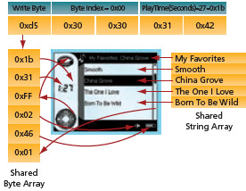
FIGURE 3 GUI Engine
The block is supplied by nearly all clocks originating from the clock generator and the power management controller. This gives maximum flexibility in clocking application-specific logic.
Six-layer bus, 15.4Gb/s bandwidth
Conventional ARM7-based MCUs have a single bus, but the AT91CAP7 customizable MCU has a six-layer advanced high-speed bus (AHB) matrix with six masters and 10 slaves that completely eliminates bus contention. Two masters are used for CPU data and instructions and for the peripheral DMA controller, and four bus masters are dedicated to the MP block, a maximum on-chip bandwidth of 15.4Gb/s. The slaves are the on-chip memories, EBI and the peripheral bus bridge, as well as four more for the MP block.
Any master can control any available bus when needed. Since there are as many busses as masters, there is never bus contention. A set of 18 interrupt lines is available for the peripherals and AHB masters implemented in the MP block. There are 14 peripheral enable lines, up to 90 dedicated I/O ports and a multiplexed connection to the USB device transceiver. This last feature allows a second, full-speed USB device or USB host to be implemented in the MP block.
DMA on all peripherals
One concern in creating a customizable MCU is that moving data between the extra peripherals or cores may overburden the device. Many ARM-based processors require the CPU to execute data transfers between the peripherals and the memories one-byte-at-a-time. A data transfer of just 4Mbs/s takes 100% of the available cycles on an ARM7 core. Clearly, a typical ARM7 MCU cannot keep up with a screen refresh data rate of 73Mbytes/s.
Atmel addressed this by putting DMA on every peripheral on the MCU and introduced a 22-channel peripheral DMA controller (PDC) that manages data transfers between the memories and peripherals independent of the ARM7. Thus, a 25Mb/s transfer between a USART and the memory can be performed by the CAP7 with 96% of the CPU’s cycles free for application processing. The MP block alone has 18 DMA channels that can be associated with high-bandwidth peripherals.
This combination of a multi-layer bus matrix and two independent memory systems overcomes the memory bandwidth problem inherent in most ARM7 MCUs.
GUI IP
Amulet’s design implements the hard macro of the GUI IP in the MP block, where it acts as a coprocessor that offloads all GUI tasks from the CPU. This frees the ARM7 core to run the embedded application code without interruptions from the screen refresh.
The Amulet approach combines hardware blocks (e.g., LCD controller, touch panel interface) with a graphical OS to render and manage the GUI, relieving some of the load otherwise placed on the CPU. Its OS has task-specific services for graphics rendering, I/O processing and general-purpose computing alongside a task scheduler.
The OS renders GUI pages containing graphic images, widgets and other objects directly to the LCD, eliminating the need for low-level code to draw to the display. The user interface is created in HTML, which is compiled into a highly compact language, microHTML, that uses much less memory. No low-level device drivers are needed to interface to the Amulet LCD controller because the included graphical OS executes the GUI directly from the compiled HTML files used to author it.
The Amulet LCD controller can drive passive monochrome or color LCDs with resolutions up to 640x480pi, or color TFT LCDs with resolutions up to 800x600pi. It handles all refresh tasks and has an internal frame buffer sufficient for small displays. Larger screens require an external frame buffer in SDRAM.
The embedded systems programmer connects the application data to the microHTML GUI through a simple API that allows read and write access to the arrays of shared data. Figure 3 shows a connection of the shared variable data to the visual GUI objects.
Emulation board-based implementation
Atmel provided an emulation board that interfaced the CAP7 MCU to an onboard FPGA where Amulet’s LCD and controller GUI OS were initially implemented and verified. Application-specific blocks were integrated into the MP block. This was achieved through placeholder instantiations of functional blocks already written into a template for the MP block’s RTL code (this was supplied by the MCU vendor). Separate templates were provided for AHB master/slave devices and for APB slaves. DMA or PDC connectivity is pre-programmed in some blocks.
The onboard FPGA was used to emulate the RTL for the Amulet IP in the MP Block, including embedded memories and external I/Os. The EBI and the external connection from the FPGA could be connected to a variety of memories on an extension board that included SDRAM as well as both NOR and NAND flash. These could be loaded with the application’s software suite and reference data. All standard interfaces that could be implemented in the MP block (CAN, USB, Ethernet, I2S, AC97, ADC, MCI, etc.) were routed through transceivers/PHYs/codecs to external connections. This enabled full test and debug of the external interfaces and networking/communication links of the device.
Source: Atmel/Amulet Technologies
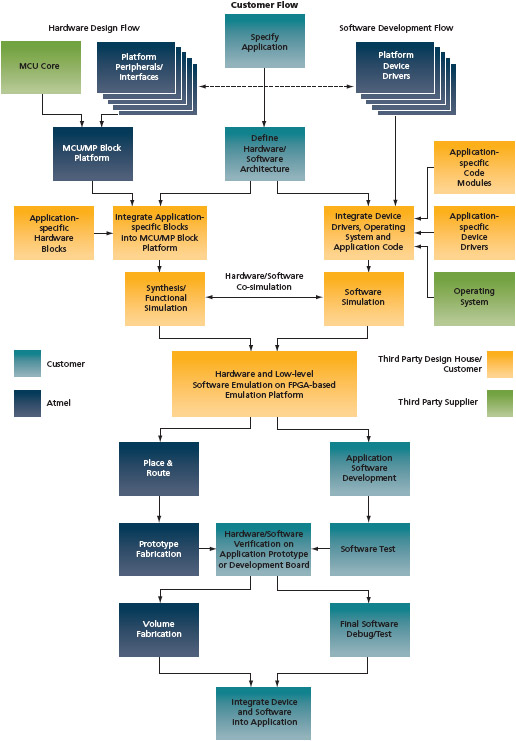
FIGURE 4 CAP7 Design Flow
All elements of the GUI were connected to onboard devices or interfaces: LCD, touch screen interface, etc. This enabled the basic elements of the GUI to be tested on board.
External PIO and FPGA input/outputs were provided for connection to application-specific external devices and the implementation of non-standard interfaces. The FPGA I/Os included a three-port USB device. A serial debug I/O connected to the PC ran industry-standard application development/debug tools.
The customizable MCU emulation board supported testing of the MCU, its peripherals and the functions implemented in the MP block, as well as all the software developed up to this point. This included the device drivers, OS port and the application code modules that control the functions implemented in the MP block.
Implementation in the customizable MCU
After successful verification of the RTL description of the LCD display and GUI OS, Atmel took control of implementing IP in the MP block on the AT91CAP7, validating the RTL, synthesizing it into a gate-level netlist using process-specific target libraries, and performing functional simulations on the entire device.
Atmel handled place and route for the MP block, using an established floorplan for its fixed portion, and also performed both post-layout simulations and static timing analysis to ensure no timing constraints had been violated. Once this was complete, the final GDSII database for mask creation was generated.
Atmel maintains pre-fabricated base wafers of customizable MCUs that are complete except for the metal layers. So, once the gate-level netlist was verified, final place and route, design finishing, mask generation and prototype fabrication took only 11 weeks. However, the Amulet design team did not have to wait on a hardware prototype to complete software development. Application software development and testing were done in parallel with the P&R and prototype fabrication (Figure 4, p.25).
Source: Atmel
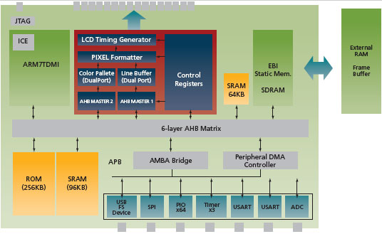
FIGURE 5 Amulet CAP7 SoC
The SoC itself
Amulet’s GUI Engine accesses the frame buffer directly via DMA for GUI rendering and LCD refreshing, leaving the CAP7’s internal memory and bus free for code execution via the ARM7 processor core. On smaller displays, the internal SRAM can be partitioned into two independent blocks utilizing separate bus slave interfaces—one connected to the Amulet GUI engine and the other connected to the ARM. This capability enables concurrent processor execution and LCD refresh with no external memory, a real benefit in applications constrained by cost or onboard real estate.
The resulting CAP7-based SoC (Figure 5) makes the addition of an interactive GUI interface to any embedded system as simple as possible for both graphic designers and embedded engineers. By implementing its GUI OS in a customizable MCU, Amulet has enabled embedded systems designers to build sophisticated, yet easy-to-use devices without fear of compromising reliability.
Atmel Corporation
2325 Orchard Parkway
San Jose
CA 95131
USA
T: +1 408 441 0311
Amulet Technologies
700 Gale Drive
Suite 190
Campbell
CA 95008
USA
T: +1 408 374 4956


