10nm processes
The 10nm generation is the follow-on process to the 14nm/16nm node and will provide a choice of either finFET or planar FD-SOI architectures. Although it is intended to provide further scaling benefits, the likely absence of EUV lithography at the point of introduction means the major challenge to 10nm processes is manufacturing cost.
Most foundries and chipmakers currently favor finFET-based processes for the 10nm generation. However, STMicroelectronics is developing a competing process based on FD-SOI. Although GlobalFoundries and Samsung Electronics have agreed to fab 28nm FD-SOI, it is not yet clear whether ST will find a production partner for its 10nm process.
At the current stage of development, the primary concern over 10nm is lithography for the finest-geometry layers and the knock-on effect on production cost.
Double patterning may not to be sufficient to pattern the densest device and interconnect layers, calling for techniques such as triple patterning if using multiple litho-etch steps or self-aligned double patterning (SADP) (see Guide). Potentially, the litho recipe may even include directed self-assembly (DSA), as outlined in this Expert Insight.
If SADP or even self-aligned multiple patterning (SAMP) is the choice, it may drive the adoption of so-called 1D layout techniques, similar to those employed by Intel for its most recent processes. In these topologies, each layer has a strongly preferred direction, with cuts used to break the pattern of parallel lines into usable interconnect fragments. In principle, because they contain a lower feature density than those used for the interconnect lines, the cut masks can be implemented using OPC techniques, potentially moving to multiple e-beam patterning. Chemical pitch splitting defines the lines themselves. This combination of different litho techniques was named complementary lithography by Intel head of lithography Yan Borodovsky.
Although triple patterning using successive litho-etch steps can achieve the layout densities required for 10nm, it may fall foul of EDA issues. Coloring for triple patterning is an NP-complete problem, making tool runtime a potential roadblock. Techniques based on two-color layout followed by correction steps that introduce a third color may provide a workaround, although these may not deliver the mask layer uniformity needed for reliable manufacturing.
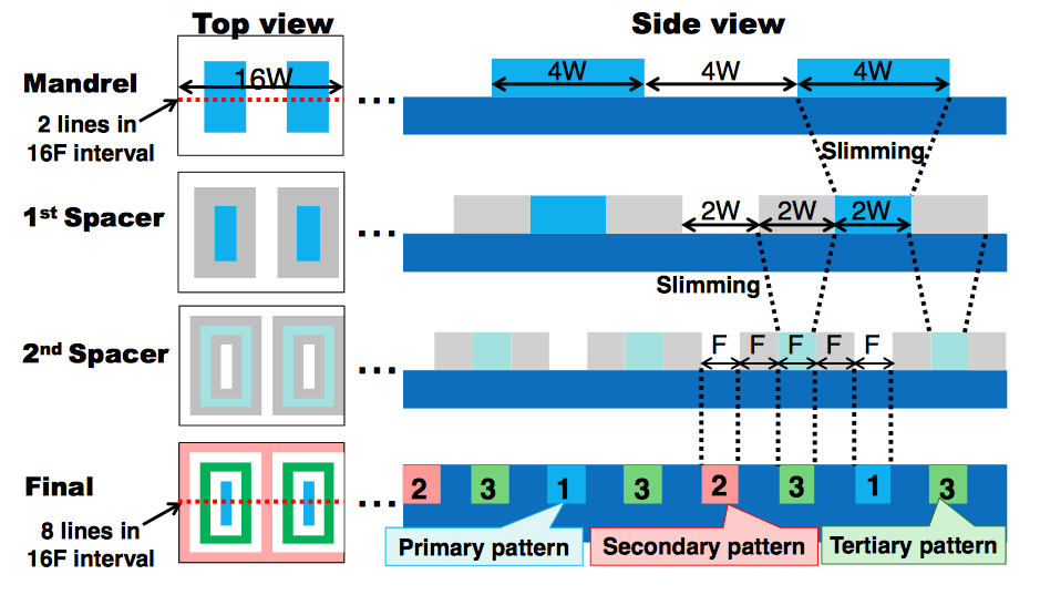
Image Self-aligned multiple patterning based on a single exposure (Source: Toshiba)
However, other techniques are being developed based on gridded routing techniques that allow two-dimensional shapes to be defined on a single layer, albeit with a greatly reduced degree of freedom compared to conventional routing – because neighboring traces need to be routed together so that the lines defined by the mandrels used as the source for pitch splitting can run in parallel. Toshiba, for example, showed a technique for this at ASPDAC 2013.
Directed self-assembly could also be introduced for 10nm together with other techniques. There are some indications that the technique could be useful for defining via layers, although there are few publicly available results.
1D design implies dramatic changes in layout styles and IC implementation. Although not broadly incompatible with EUV patterning, these changes may not make best use of EUV if the technology is introduced after the initial introduction and production ramp of 10nm processes.
In terms of design, the reduction in pitch for the lower metal layers will further increase interconnect resistance. According to the International Technology Roadmap for Semiconductors (ITRS), total wire length within an SoC has increased 60 per cent in five years to more than 3km/cm2. New materials being considered for the 10nm could ameliorate the problem but the likelihood is that designers will have to make use of upper metal-layer interconnect to support high-speed, longer traces, which will increase effective congestion possibly already worsened by the use of SAMP/pitch splitting and 1D design.
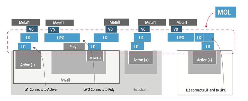
Image Introduced at 20nm, local interconnect is likely to be important for 10nm processes (Source: Cadence)
So-called middle-of-the-line (MOL) interconnect, first introduced for mainstream production at 20nm, can help reduce congestion for short, local routes. MOL sits below the first metal layer and can be considered an extension to polysilicon local interconnect. Although MOL routing calls for multiple masks, it is cheaper to implement than traditional metal layers because it does not employ vias. The interconnect lines connect the upper and lower layers and on to the polysilicon contacts using shape overlap.
For finFET-based processes, the additional layers are known as CA and CB. CA is used to route vertically, typically connecting the fins of the same FET together or to make power and ground connections to the transistors. CB is used horizontally within the cell, linking points in the contact layer to poly.
Constraints imposed by SAMP are likely to drive changes in standard cell design to improve cell pin access. Some of the routing considerations for MOL are considered in this article by Cadence looking at its introduction in the 20nm generation.