Verifying clock domain crossings when using fast-to-slow clocks
A look at three techniques to verify the validity of signals moving between clock domains
Checking that asynchronous signals cross clock domains correctly means identifying the data and control paths, and ensuring that the receive clock domain data flow is controlled by a multiplexer with a select line fed by a correctly synchronized control line.
Tools such as Real Intent’s Meridian CDC can identify all the data and associated control paths in a design, and ensure that the control signals passing from a transmit clock domain to an asynchronous receive clock domain are correctly synchronized. The tool uses three techniques to achieve this: structural checking, formal checks and simulation-based injected metastability checks.
Structural checking
Structural checking does not care if asynchronous transitions are slow-to-fast clocks or fast-to-slow clocks. It ensures that all transitions are correctly synchronized by having the appropriate synchronizer flops. From a structural perspective, the entire design can be checked in one run and all the clock domain transitions are checked for correctness. For example, the clock domain crossing (CDC) in Figure 1, has a transmit clock Clk1 on the left (with the orange flops), and a receiving clock Clk2 on the right (with the blue flops).
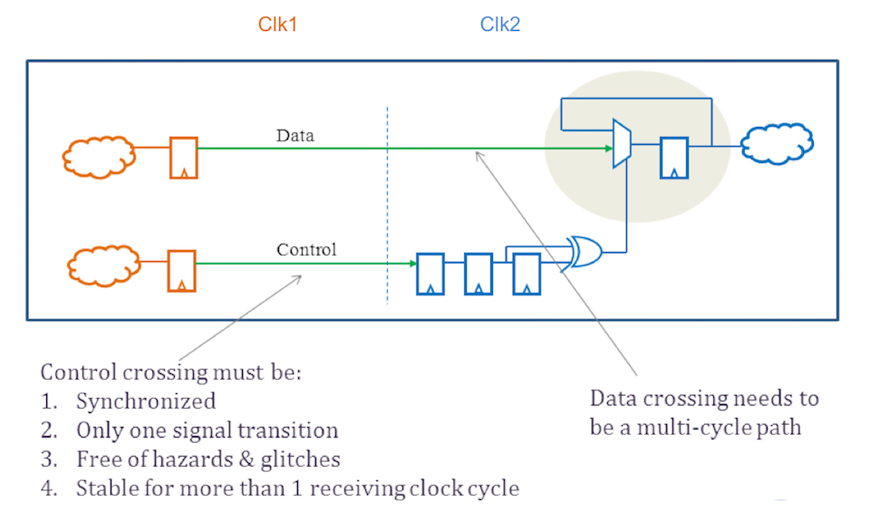
Figure 1 A typical synchronized control and data clock domain crossing (Source: Real Intent)
Figure 2, in which positive-going clock edges are shown by the vertical lines, illustrates that this approach works well for a slow-to-fast clock transition. Any change of a control signal in the slow domain is always captured by one of the edges of the receive domain clock, Clk2, before Clk1 causes the control signal to be released. This occurs because Clk2 is faster than the transmit domain clock, Clk1. Also, for slow-to-fast clock transitions the data is typically stable long enough to be captured and transmitted to the receive domain. In Figure 2, the possible Clk2 edges that could capture the TX CNTL signal in RX CNTL Sync2 flop are shown with dashed vertical lines.
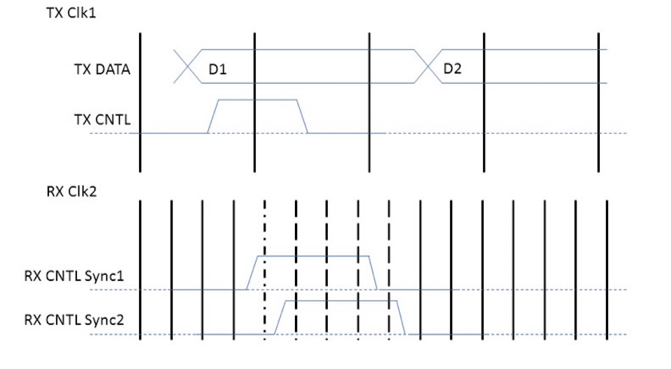
Figure 2 Slow-to-fast clock crossing. (Source: Real Intent)
Figure 2 – Slow-to-fast clock crossing. There are many possible clock edges, shown dashed, of RX Clk2 that can sample the value held in the TX CNTL flop. The dot-dash edge is the first possible transition into Sync1, and dashed edges are transitions into Sync2. There is no issue with the TX CNTL period as long as the signal is sampled by one clock edge of TX Clk1.
The situation is different in a fast-to-slow clock domain crossing. When there is a fast-to-slow transition, a short control pulse could be completely missed by the receive domain. For example, in Figure 3 the much slower receive clock, Clk2, is unable to capture the TX CNTL signal, even if it is held in a flop triggered by the much faster transmit domain clock, Clk1, because the TX CNTL signal is released after just one period. That does not give Clk2 a chance to capture the value held in the TX CNTL flop into RX Sync1 and, therefore, not into RX Sync2. To address this concern and others that cannot be dealt with by a purely structural CDC check requires formal analysis.
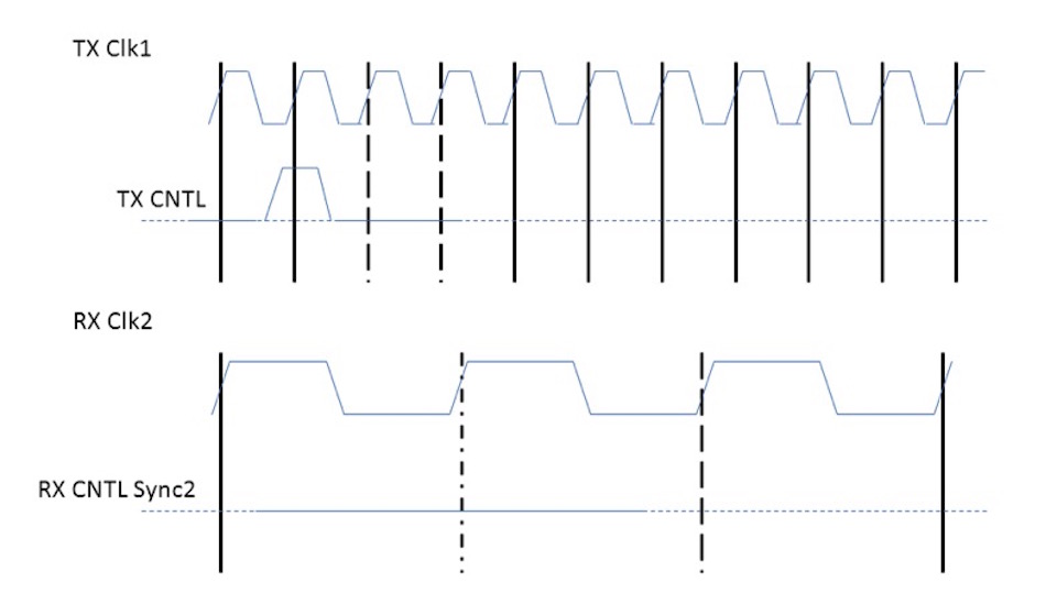
Figure 3 Fast-to-slow crossing with short CNTL pulse (Source: Real Intent)
Figure 3 – Fast-to-slow crossing with short CNTL pulse. The TX CNTL pulse, which is successfully sampled by TX Clk1, is cleared in the TX CNTL flop before it can transition into the RX Clk2 domain. The control pulse is lost because it is insufficiently wide. A check is needed on to ensure the pulse is wide enough.
Formal checks are also necessary on a slow-to-fast data crossing with feedback. In such a circuit, as shown in Figure 4, an acknowledge signal coming from the receiving fast-clock domain to the transmitting slow-clock domain also requires a formal pulse width check.
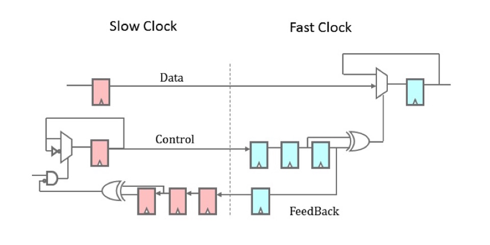
Figure 4 Slow-to-fast clock crossing with feedback (red flops are slow clock, blue flops are fast clock)
Although the control pulse (request) is going from slow to fast and does not need a formal pulse width check, the acknowledge pulse width check is necessary because the acknowledge signal (the feedback circuit) is going from a fast to a slow clock and, in order for the acknowledge to be properly captured, the acknowledge pulse (transmitted from the receiving side) must be sufficiently wide to be captured (received on the transmitting side) by the slower clock domain of the transmitting side flops.
Failure to check for this condition causes many request/acknowledge circuits not to work as expected. Note that feedback circuits in a fast-to-slow crossing are operating in a slow-to-fast mode and the acknowledge signal in such a circuit does not need to be pulse-width checked. In short, all fast-to-slow control signal transitions, whether connected in a feed-forward or a feedback manner need to be formally pulse-width checked to ensure integrity of the control aspect of the clock domain crossing.
Formal analysis
To check if the fast-to-slow clock domain crossings have control signals that can be captured by the receive domain clock, Meridian CDC offers a formal analysis capability for asynchronous clock domain crossings. There is a requirement that the control pulse in the fast transmit domain must be of a certain minimum width in order to be captured by the slower receive domain clock. Figure 5 shows that TX CNTL must be held high for several clock periods of Clk1 for the TX domain flop value to be captured by the RX domain Sync1 flop and then passed into RX domain Sync2 flop.
A formal check called PULSE_WIDTH verifies that the transmit domain’s control pulse is long enough to be captured by the receive domain’s clock in all circumstances. It examines all the pulse-generation logic and takes into consideration the clock frequency ratio during detailed formal analysis to determine pass or fail. If the pulse length is insufficient, a counter example is generated to show the circumstances in which this would occur. If PULSE_WIDTH passes, the crossing shown always has correct control pulse duration to ensure there will not be a missed control pulse.
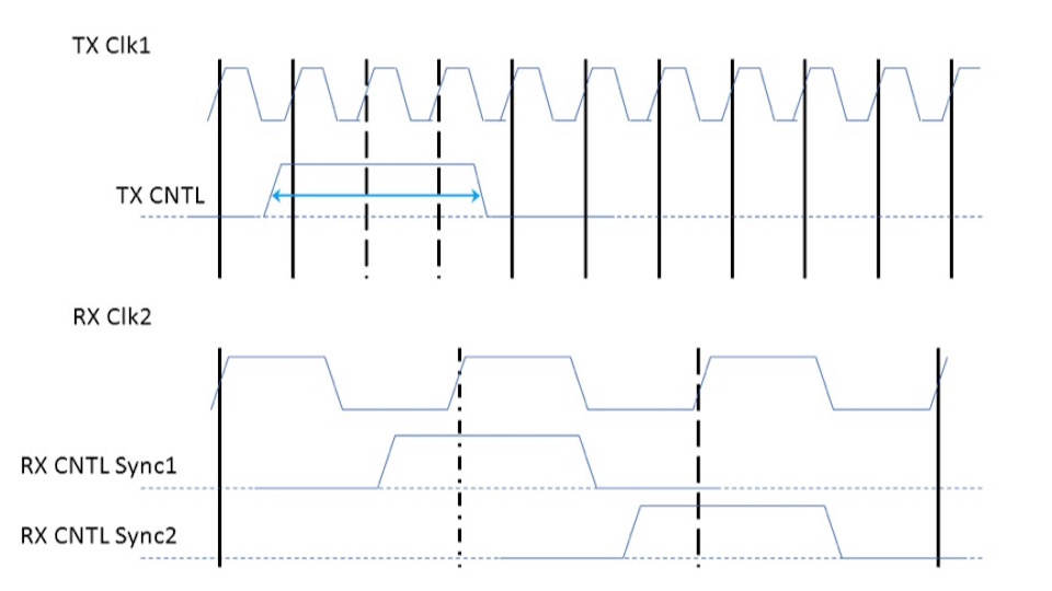
Figure 5 Fast-to-slow clock domain crossing with sufficient pulse length (Source: Real Intent)
Figure 5 – Fast-to-slow clock domain crossing with sufficient pulse length. Here the TX CNTL pulse is held high for a sufficient number of TX Clk1 periods so that an edge of RX Clk2 is able to sample the value on the TX CNTL flop into the RX CNTL Sync1 flop, which then can pass the value to RX CNTL Sync2. This can be formally proven using the PULSE_WIDTH check of Meridian CDC.
The data path also needs checking, since it is possible that if the data is not held stable for a long enough period, it might get missed in the receive domain. For example, suppose the transmit domain has the data sequence <D0><D1><D2><D3>, etc., as in Figure 5. If the data changes before the control signal has been passed to the receive domain, the receive domain may miss some data and end up with <D0><D1><D3>…. An additional formal check in Meridian CDC called DATA_STABILITY ensures that the data transitions slowly enough to be captured by the transmit domain clock and then transferred to the receive domain. Only a formal check using full sequential analysis of behavior can do this correctly.
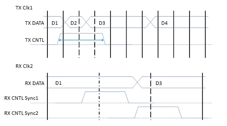
Figure 6 Fast-to-slow clock domain crossing with data instability (source: Real Intent)
Figure 6 – Fast-to-slow clock domain crossing with data instability. The data must be held stable long enough to be captured by the receive clock RX Clk2. If the data changes too quickly, some of it may be missing in the receive clock domain, as shown in the receiving clock domain data stream. This can be formally proven using the DATA_STABILITY check in Meridian CDC.
Formal checks need more information than structural checks. In structural checking, the environment can be captured automatically with little user input for resets and clocks. In formal checks, all the reset signals must be very accurately associated with their corresponding clocks. All clock frequencies must be specified for the appropriate formal checks to be made on the fast-to-slow clock domain crossings. This makes setup for formal checking more complex and requires detailed design knowledge about all the frequencies of clocks and combinations of those frequencies. For example, multi-mode designs also need the selection signals for mode selection to be specified by the user. Where appropriate, automatic multi-frequency analysis also can be addressed by the formal engines within Meridian CDC.
Metastability-aware simulation
Regular simulation testbenches don’t explore what could happen to the design if there was metastability in the data or control paths. After structural analysis has shown that all crossings contain synchronizers, and formal analysis has shown that the pulse width and data are stable, a whole-chip metastability-aware simulation is needed to see if the design is still sensitive to metastability.
The SimPortal feature of Meridian CDC can instrument a design with functional monitors and metastability checkers, as shown in Figure 6. The design is not changed – instead the necessary monitors and checkers are written in an auxiliary Verilog simulation testbench file, which is referred to by the original simulation testbench when metastability checking is invoked.
Figure 7 Metastability-aware simulation (Source: Real Intent)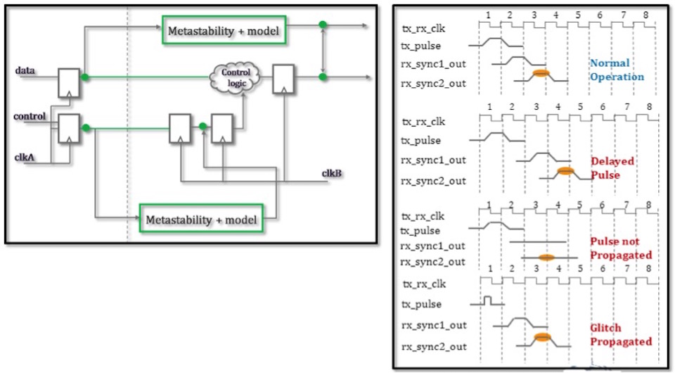
Figure 7 – Metastability-aware simulation checks the tolerance of downstream logic to jitter in the data path using functional monitors and CDC checkers.
SimPortal can randomly inject jitter onto the control or data crossings to mimic metastability, and produce simulation checkers to catch violations during simulation.
Conclusions
As the number of clock domains in designs rises, so does the importance of checking that signals, especially those moving from fast to slow domains, transition between domains as intended.
This article has outlined three steps to making these checks;
- Use structural checking to ensure that all data signals crossing domains are switched via a control signal that has the appropriate levels of synchronization.
- Use formal verification on all CDC crossings to ensure control signals have a sufficient pulse width to enable the receiving domain clock to capture the transmit domain’s control pulse. This is especially important for fast-to-slow clock domain crossings. Use formal analysis to examine the data transitions for data stability.
- Use metastability-aware simulation on the entire design with an existing simulation testbench to insert random metastability into data and control crossings. Run the simulation against specialized checkers that are automatically generated to prove that the design is not sensitive to metastability.
Once these steps have been taken, designers should have greater confidence that fast-to-slow clock domain crossings have been analyzed correctly.
More info
[1] http://www.realintent.com/real-intent-products/meridian-cdc/
Author bio
Dr Roger B Hughes, director of strategic accounts, Real Intent, is a renowned international expert in formal verification technologies and has over 20 years’ experience in the EDA industry working both at start-up companies in lead engineering roles and publicly traded companies in managing and directing technical product development. He obtained his electronic engineering degree at University of Wales, Swansea and his Masters in digital systems and his PhD in electronic engineering at Brunel University, UK. He has published over 70 papers.
