Using the MIPI RFFE specification to simplify the control architecture of multi-radio SoCs
The MIPI RFFE standard provides a common approach to controlling power amplifiers, low-noise amplifiers, filters, switches, power management modules, antenna tuners and sensors in SoCs and systems.
Smartphones and tablets have conditioned people to expect that they can have access to any information they want instantly, anytime and anywhere. Fast wireless network technologies such as LTE and IEEE 802.11ac are helping to meet that expectation. Fifth-generation cellular standards will raise the bar for designers tasked with enabling such instant gratification, by pushing download speeds into the Gigabit per second range and latencies into single-digit milliseconds.
This combination of rising user expectations and continuous network improvements creates major challenges for systems designers, who must find ways to keep their devices from becoming the bottleneck. Overcoming these challenges is particularly important when their devices are aimed at businesses and consumers who are willing to pay a premium for performance.
The multi-radio interface challenge
Meeting these requirements typically involves increasing the bandwidth available to the device by adding more transmitters and receivers, each of which has external front-end (eFEM) components controlled over general-purpose inputs/outputs (GPIOs). The combination of more external units, greater multi-band support and improved functionality increases package pin-outs and routing complexity, which in turn affect the device’s form factor, cost and market potential.
For example, a 2×2 Wi-Fi/Bluetooth solution uses 17 pins – 13 discrete control pins and four analog pins – to support up to four eFEMs: two for Wi-Fi Low Band (LB) and two for Wi-Fi High Band (HB). Figure 1 illustrates this architecture.
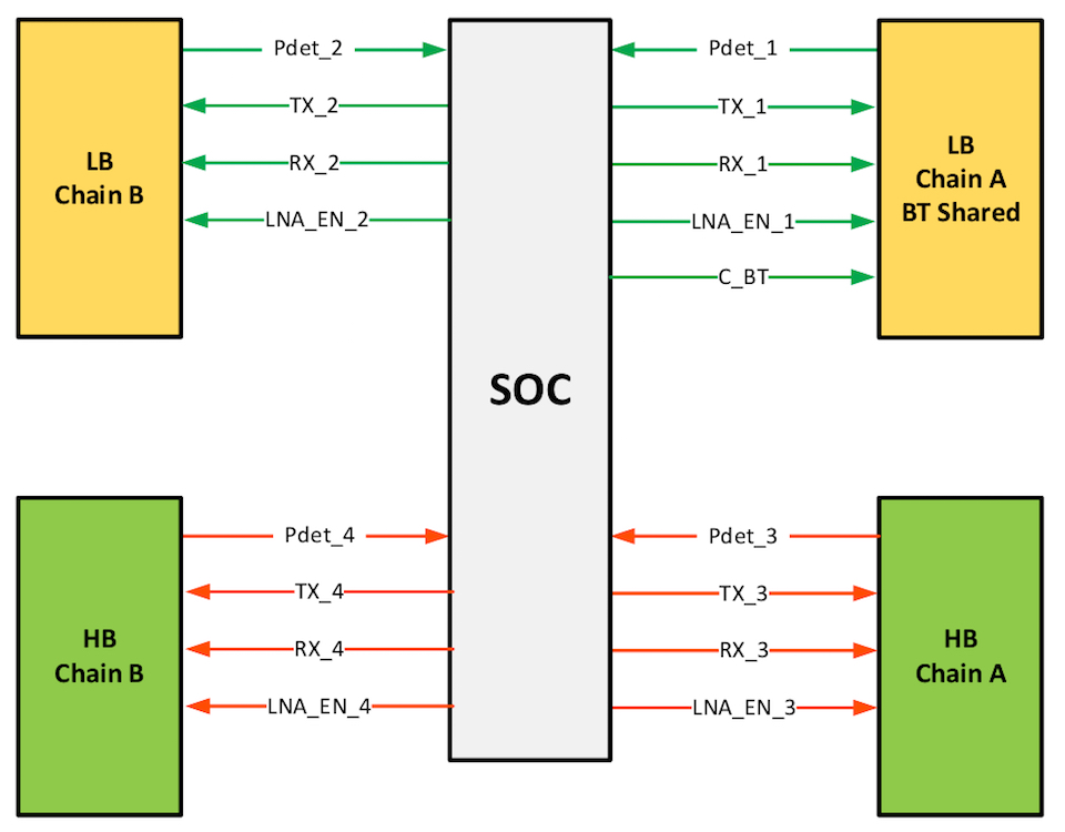
Figure 1 Supporting multiple radios in an SoC soon leads to a surfeit of control lines (Source: MIPI Alliance)
What systems designers need is a serial communication interface to control external/peripheral RF components for Wi-Fi and Bluetooth devices. Serial communication adds a time overhead for each configuration, so the interface needs to include a master-slave mapping architecture that minimizes the number of telegrams necessary to control single input, single output; multiple input, multiple output ; and concurrent dual-band use cases.
MIPI’s simplified RF front-end control interface
That’s why the MIPI Alliance developed a specification for an RF Front-End control Interface (RFFE). Most current approaches to controlling RF front-ends are either proprietary or de-facto, which undermines scalability, economy and compatibility. The MIPI RFFE approach provides a common approach to controlling power amplifiers, low-noise amplifiers, filters, switches, power management modules, antenna tuners and sensors – whether each function is in a separate device or all the functions are integrated into one.
MIPI RFFE supports a variety of master-slave configurations, from 1:1 to multiple masters with up to 15 slaves. This flexibility enables designers to accommodate each application’s functional and performance needs. Because the implementation of digital logic can be costly, the RFFE specification includes a minimum configuration for slave control that can be implemented using just 300 to 500 gates.
Many RF applications require time-accurate control, which RFFE addresses in two ways: by using a relatively high bus clock of 26MHz, and by introducing time-accurate triggering mechanisms to control timing-critical functions in multiple devices. This architecture is command driven, based on an assumption that a simple slave lacks the required timing accuracy.
The MIPI RFFE specification defines read/write command sequences with five address bits, enabling access to 32 different one-byte registers. The specification divides the register address space into reserved registers (used to store special modes, group triggers and slave/manufacturer IDs), and user-defined registers that enable slave functionality. User-defined register 0 can be accessed with a special command to enable faster write telegrams to that address.
Taking control of eFEM configurations
Today, eFEMs are controlled by discrete signaling. eFEM vendors have chosen common configurations for various eFEM system modes. Figure 2 illustrates example eFEM modules for LB and HB, and Table 1 lists the control configurations used on LB and HB eFEMs, showing all the LB and HB system modes.
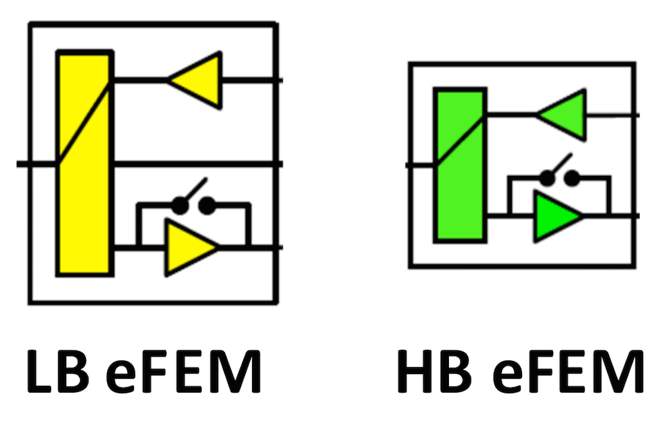
Figure 2 The architecture of possible LB and HB eFEM modules (Source: MIPI Alliance)
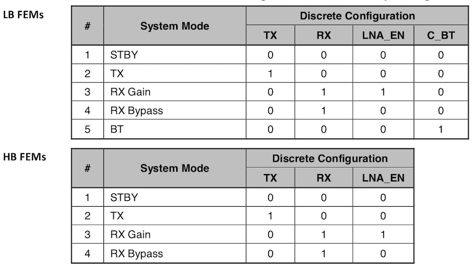
Table 1 Control configurations commonly used on LB and HB eFEMs (Source: MIPI Alliance)
The MIPI RFEE specification enables eFEM control by issuing a direct register write to each eFEM with the desired system-mode code. For example, to move HB chain A eFEM to TX, 0x08 is written to a pre-defined register, and then the eFEM switching is done according to the transmitted system-mode code. However, this method is inefficient because it requires a dedicated transaction for each eFEM module. Moreover, only three or four bits out of eight are used for configuration on each write transaction.
Another mapping scheme would use register 0 bits [6:0] to hold two coded words: a three-bit word for LB (encoding the five LB system modes) and a two-bit word for HB (encoding the four HB system modes). Using this approach in broadcast mode would enable separate configurations of LB and HB eFEMs in one telegram. However, if the goal is to configure two eFEMs on the same band (i.e., two LB eFEMs, or two HB eFEMs), then two or more telegrams must be issued, which would increase the control signaling overhead accordingly.
To avoid these issues, a third mapping scheme would increase flexibility for issued telegrams and ensure that transitions between all system modes can be made using one telegram, without imposing the need to implement a complex triggering mechanism on the eFEM side. In this mapping, only the register 0 (Reg0) write, register write and broadcast capabilities have to be supported.
RFFE control register features
MIPI RFEE has two control registers, with part of the MIPI RFFE register address space reserved for system-mode discrete configuration (which is uploaded upon initialization to the eFEM):
- Register 0 is defined as the pointer for different system modes, i.e., register 0 points to the relevant eFEM configuration stored on the eFEM at initialization time. Seven register 0 bits are divided into two pointers: four bits for an LB pointer, and three for an HB pointer. This enables the controller to set different system modes for the LB eFEMs and for the HB eFEMs. Broadcast telegrams can be issued in real time to configure all eFEMs to a given system mode.
- Register 1 enables or disables each eFEM, making it possible to enable any combination of the connected eFEMs. If register 1 is disabled, it is also necessary to reset register 0 to ensure that when the eFEM is enabled, it will point to a valid state. Register 1 enable/disable bits can be mapped to enable single-telegram configuration using broadcast.
- The rest of the registers span the LB and HB system modes, taking into account combinations of any subset of the eFEMs, as well as all of the possible Wi-Fi/Bluetooth coexistence modes.
MIPI RFFE telegrams are generated in real time according to the eFEM configuration command required for the desired system state: Wi-Fi TX mode, Wi-Fi RX mode, Wi-Fi/Bluetooth simultaneous mode or Bluetooth standalone mode. On the SoC side, the current eFEM status, operation modes and system modes, are all stored first. Next, the SoC generates one or more MIPI RFFE telegrams as necessary whenever a new eFEM configuration command is issued.
A change triggering such RFFE telegrams can be caused by enabling or disabling any subset of the connected eFEMs, changing the eFEM system mode, or a combination of both .
Conclusion
The development of the RFFE standard by the MIPI Alliance has consolidated many aspects of the set-up and control of multiple radio front-ends into a single, consistent definition that should simplify both the hardware to implement control of radio front ends and the software to configure them. For a deeper dive into how the specification works, as well as its additional benefits, download the white paper at http://mipi.org/sites/default/files/whitepapers/mipi_RFFE_White-Paper_Wi-Fi-Bluetooth_v1-0.pdf.
Author
John Oakley is RFFE Working Group Vice Chair for the MIPI Alliance.
