Using assertions in ‘elemental analysis’ for airborne hardware development – Part Two
The article continues the discussion of the verification requirements within the RTCA DO-254 design assurance guidelines. Part Two focuses on assertion-based verification. It proposes a method for using ABV to meet ‘elemental analysis’ requirements and underpin a systematic approach to robustness testing.
Part One of this article discussed the RTCA DO-254 Design Assurance Guidance for Airborne Electronic Hardware. We described how the standard requires elemental analysis during verification, which is typically addressed with attempts at code coverage. Here, we introduce the technique of assertion-based verification (ABV), showing how it can satisfy elemental analysis and boost testing robustness.
Assertion-based verification
As a concept, ABV is more than 20 years old and already widely used in electronics system design (by nearly 70% of the industry, according to one study1). It is based on assertions that are concise lines of code describing how a design is supposed to work. Comments have done this historically but they are passive; assertions actively monitor that a design does what the assertion says it should. Assertions should therefore be closely tied to design requirements. Used in this way, they can constantly monitor not just requirements but also behaviors throughout verification.
Both designers and verification engineers write some of the assertions. These are low-level assertions into RTL code or a separate file at the block-level to verify various aspects of an implementation. Here, assertions perform early ‘white-box’ testing by providing visibility into what is going on in the code. Similarly, designers can write assertions to verify interfaces. This might be frowned on in a DO-254 flow for not being strictly independent from the design, but the standard does recognize the value of early verification2.
Verification engineers then also write assertions in the test environment — independent of the RTL code and the design spec — based on the system and/or derived requirements. Here, assertions act as ‘black-box’ agents that actively monitor requirements. By also adding a ‘cover’ statement to the assertions, the conditions they monitor can be tracked and tallied for requirements coverage reports.
Figure 1 shows a requirement along with its corresponding assertion. The assertion is written in SystemVerilog, and that and the other language normally used, PSL, are discussed in the next section.
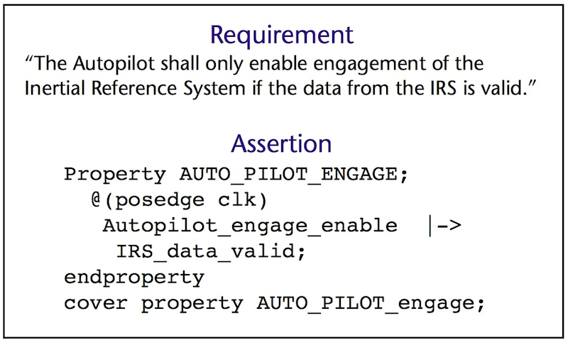
Figure 1
Requirements-based assertion (Source: Mentor Graphics/Boeing – click image to enlarge)
This assertion says that when the Autopilot_engage_enable signal goes active, the IRS_data_valid signal should already be valid. If the assertion fires – indicating a violation –a verification tool can examine the assertion and all threads associated with it to identify the exact situation that caused that firing.
IEEE standard languages and industry usage
The widespread adoption of assertions flows directly from two IEEE-based standards.
The first and most widely used is SystemVerilog and from that are derived SystemVerilog assertions (SVA). The format is loosely based on the Verilog design language and uses Verilog-style operators.
The second and slightly less popular standard is the Property Specification Language (PSL) assertion format. PSL is more popular among designers using the VHDL design language, as one flavor of PSL uses operators similar to VHDL.
The two languages are similar enough in most respects that we can use them interchangeably, as the simple example and comparison in Figure 2 shows:
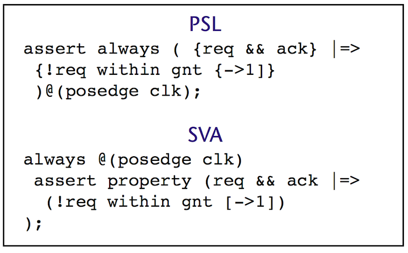
Figure 2
Checking a ‘request acknowledge handshake’ as expressed in PSL and SVA (Source: Mentor Graphics/Boeing – click image to enlarge)
The above assertions do exactly the same thing. They check a ‘request acknowledge handshake’, a commonly used design interface. When one block wants data, it will assert the request (req) signal. The attached block will service this request when it can, and will indicate this with the associated acknowledge (ack) signal. This assertion checks that, once the ack response is given, the req signal must drop within one clock cycle. In this type of handshake, it will usually cause problems if the request signal continues to be held after the acknowledge signal has been provided.
Assertions tied to requirements and coverage
In DO-254, requirements are central to the design and verification process. Assertions fit nicely into this environment because they are extremely flexible and can monitor low- to high-level behavior across any part of the design.
Assertions require the user to be specific. For example, if a system requirement states, “The flight crew shall be aurally warned if the landing gear is down but not locked,” the vagaries of English become apparent. How quickly after the lock failure does the alarm need to be sounded? How is a lock failure indicated to the design? When an associated assertion is created, the assertion language demands specifics. Consider how this scenario is expressed in Figure 3.
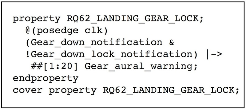
Figure 3
Assertion for landing gear lock (Source: Mentor Graphics/Boeing – click image to enlarge)
By looking at this assertion, we now know the associated design I/O pins involved, and the timeframe (within 20 clock cycles). Also note that the assertion includes a name: RQ62_LANDING_GEAR_LOCK. This name should correspond to the hardware requirements document. When verification yields that the associated behavior is correctly performed, the assertion will be marked as ‘covered’, and the associated point in the coverage database will be tagged. A user can view the coverage for this specific item by looking at RQ62_LANDING_GEAR_LOCK in the database. (Some tools make this quite simple by linking the database, verification tool, and requirements).
By writing requirements as assertions, the engineers are forced to identify all the information that makes the requirement verifiable, which is part of a requirements validation process. So writing requirements as assertions supports requirements validation activities. This alone can improve design quality, and reduce design and verification schedules.
Requirements-based tests typically only check the design behavior of the associated requirement being stimulated. Any anomalous behavior associated with other requirements could be missed. But requirements-based assertions can be watching constantly across all requirements-based tests. This means that, if another test stimulates anomalous behavior, it will be detected by the assertion.
Even if it is typically not possible to write every requirement as an assertion, writing a significant portion as assertions can enhance requirements validation and improve verification.
Assertions tied to the design implementation
Each decision during design has implications, and can lead to downstream implementation decisions. Designers are usually conscious of these decisions as they are made, as well as the tradeoffs in other possible implementations. During this process, there are many situations where corner-case behaviors are created within the implementation.
For example, imagine a designer is creating a FIFO. The obvious FIFO corner cases that need to be handled are:
1. Enqueue when the FIFO is full
2. Dequeue when the FIFO is empty
3. Simultaneous enqueue and dequeue
In a case like this, the designer should add the necessary logic to allow the FIFO to behave gracefully should any of these corner cases be encountered. The crucial question is, “Will the designer’s logic operate correctly when confronted with these corner case scenarios?”
If the designer is using an ABV methodology, they can add assertions to the FIFO code as they create it. They can add coverage statements that are triggered when the simulation test stimulates a FIFO dequeue with simultaneous enqueue, as well as the other two cases above.
The assertion code that follows in Figure 4 will monitor the simultaneous FIFO enqueue and dequeue, and indicate when that corner case has been attempted. Other assertions or the test itself will then check to verify the FIFO acted correctly in the presence of this scenario.
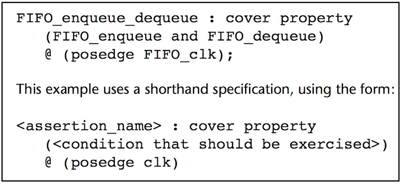
Figure 4
Assertion to monitor simultaneous FIFO enqueue and dequeue (Source: Mentor Graphics/Boeing – click image to enlarge)
The @(posedge clk) tells the assertion to only check once per clock cycle when the data will be stable. This is the same time data that is loaded into registers, and better prevents false triggering due to normal but spurious combinational logic changes in-between clocks.
We have discussed the importance of anomalous behavior propagating to an observable point in the design. In typical requirements-based testing, the observable point is typically the output pins of the design (Figure 5).
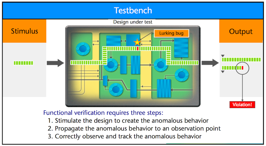
Figure 5
Verification without ABV (Source: Mentor Graphics/Boeing – click image to enlarge)
But, by placing these assertions close to the design element, any anomalous behavior can be immediately detected with no need for further propagation (Figure 6).
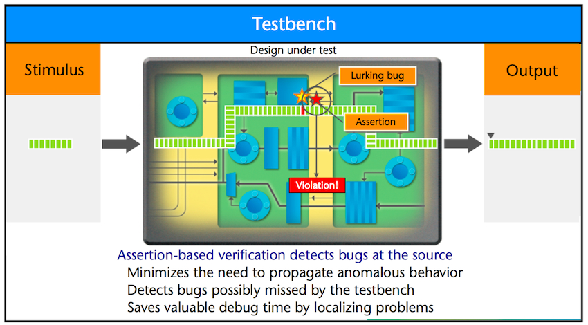
Figure 6
Verification with ABV (Source: Mentor Graphics/Boeing – click image to enlarge)
For example, an assertion can be added to ensure the FIFO does not try to add more data to a full FIFO. The enqueue_enable signal in Figure 7 indicates data was loaded into the FIFO. So this checks that if the FIFO is already full and another write request comes in, it is not honored until a slot is available in the FIFO).
But, by placing these assertions close to the design element, any anomalous behavior can be immediately detected with no need for further propagation (Figure 6).
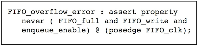
Figure 7
Assertion to ensure FIFO does not add to a full FIFO (Source: Mentor Graphics/Boeing – click image to enlarge)
Another assertion can be added to ensure that this overflow condition was attempted during simulation test (obviously Figure 7’s error scenario cannot be seen unless the associated corner case is stimulated).
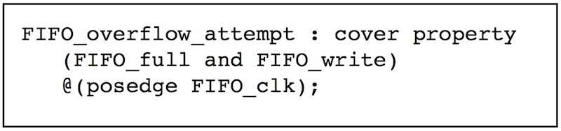
Figure 8
Ensuring overflow condition attempted during simulation test (Source: Mentor Graphics/Boeing – click image to enlarge)
Assertions such as these are straightforward to add, but it is important that this is done when a designer is creating the design and while he or she is thinking about these potential corner cases. However, not all designers are sufficiently comfortable with the assertion languages to simply write them at the same time they write their HDL code. Creating an assertion might cause a designer to need to refer to a reference guide or other training material. This can break the designer’s flow of concentration, and is not recommended. Instead, the designer should simply add a natural language comment in the design with the idea for the assertion.
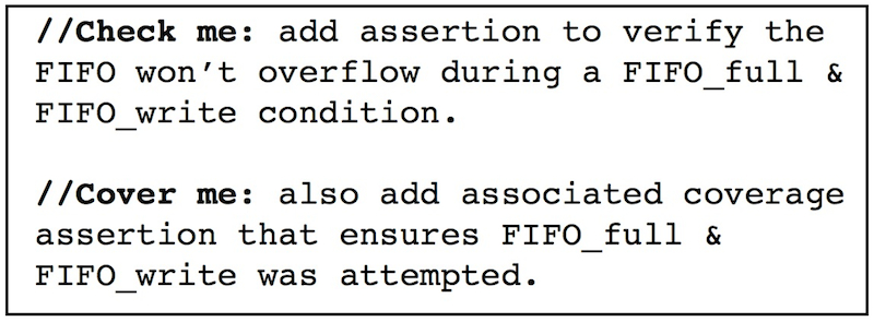
Figure 9
Comments to prompt the later addition of assertions (Source: Mentor Graphics/Boeing – click image to enlarge)
As you can see, such comments have a regular expression at the front: //Check me: or //Cover me:. They should be consistent across the design so they can be searched for and replaced by the assertions that implement them. The comments can also be left after the assertion is added to better describe what the assertion is checking. Simply change the keyword, as in Figure 10.
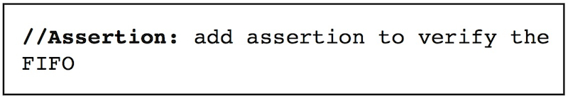
Figure 10
Describing an added assertion (Source: Mentor Graphics/Boeing – click image to enlarge)
Elemental analysis
In general, a reasonably well-instrumented design should roughly contain one assertion per 100 lines of RTL (excluding comments). This number can vary, depending on the complexity of the assertions, and the complexity of the logic being checked. There is at least one tool3 on the market that will check for ‘assertion density’ within a design. This measurement identifies the average sequential distance from each register to an assertion (Figure 11).
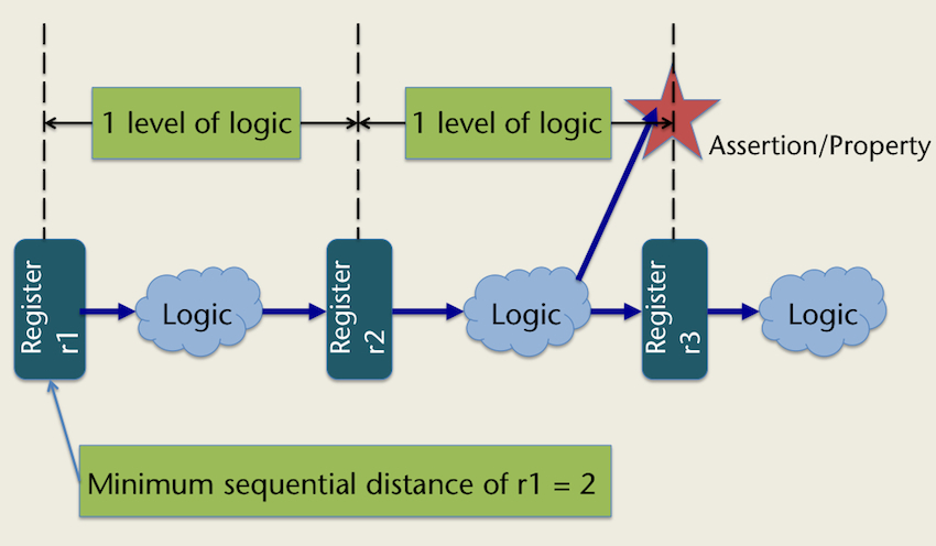
Figure 11
Assertion density (Source: Mentor Graphics/Boeing – click image to enlarge)
To describe assertion density, imagine a person walking to their car in a large dark parking lot. Not all potential dangers can be seen. If a single light is added in one area of the parking lot, it will have greater visibility, but other areas will remain dark and potentially dangerous. As an analogy, assertion density is a measure of the number of lights (assertions) in the parking lot (design). In some cases, the lot is a large, flat, and open, so a few lights are all that is needed. But, if the lot has a variety of potential hiding places, such as trees, small buildings, or other large vehicles, more lights are needed. A large, flat, open parking lot is equivalent to a datapath type design with little control logic, and therefore fewer corner cases that need to be observed with assertions. Trees, buildings, or other vehicles are equivalent to corner cases within control logic where design errors can hide. In this case, additional assertions are needed to add visibility to these areas of the design.
Defining an ‘element’
An ‘element’ is essentially any ‘unit’ that needs to be actively designed and included. This might sound overly simplistic, but the concept is important to grasp. When a design engineer creates a design, he or she does not think in terms of the lines of code. Instead, a designer ‘sees’ pieces of functionality needed that will work with all the other pieces to perform desired actions. An element is also anything in the design that needs to be checked or covered (including its interactions with connecting elements). This matches the definition of assertion-based verification.
If a design is well instrumented with assertions to monitor coverage and watch for errors, then its elements are well instrumented. When tested in simulation, if all assertion coverage points are covered, and no error assertions flagged errors, then the elements of the design are working properly. Therefore, if a design is well instrumented, it stands to reason that ABV can be directly applied to DO-254 credit toward elemental analysis.
Example process: ABV for elemental analysis
As stated earlier, Design Assurance Level (DAL) A and B designs (those for which the effects of failures are most severe) require further analysis, such as elemental analysis. Elemental analysis helps ensure the verification closure of requirements-based testing. ABV provides a good verification completeness metric when it is done properly.
This caveat means using ABV toward elemental analysis requires additional methodological steps to ensure assertion completeness and correctness.
- All designers and verification engineers should be trained in and skilled at using assertions, or must have access to similar expertise elsewhere within the project team.
- All design engineers must follow the process of adding assertions as they design their code (or, if they prefer, adding English comments to their code that can be converted into assertions). The comments should be added using a common expression such as //check me: <comment> or //cover me: <comment>.
- All assertions should be reviewed during the regular code review4 process. In addition, the design should be reviewed for any missing assertions. Any assertions that are deemed overly complex should be simplified into multiple smaller assertions to avoid creating incorrect assertions.
- Assertion density metrics or specific coverage assessments should be collected (by counting assertions-per-lines-of-code, or use of a density metric, or driven by specific criteria).
- Assertion coverage results should be aggregated across all requirements-based simulation tests, and any uncovered items should undergo further analysis. These uncovered items are an indication of:
- Necessary code that lacks a requirement and associated test (so the missing requirement and associated test should be added).
- Some kind of anomaly that needs further analysis and possibly needs to be excluded (such as some types of error scenario recovery or test-only logic).
- Unnecessary code (which should be removed)
- The simulator should be set to prominently display any assertions flagging unexpected errors in the design. All requirements-based tests should pass with no ‘check’ assertions firing but all coverage assertions satisfied.
ABV vs. code coverage for elemental analysis
Verification engineers on complex commercial electronics designs view line coverage (or, more specifically, statement coverage) as their first means of determining verification effectiveness. However, most do not focus on specific lines lacking coverage. Instead, they use higher-level analysis, identifying blocks or areas within the design that have low coverage, then work to understand and improve their testing deficiencies. Some will collect additional coverage metrics, such as branch/decision coverage.
It’s recommended that an applicant follow this same approach as part of a holistic verification closure approach. Additional thought and research is required before ABV can or should be used stand-alone as a verification closure metric toward elemental analysis.
Summary
Code coverage as a verification completeness metric has limitations when applied to elemental analysis. ABV, when used properly, can provide significantly better verification completeness. It can be used to map directly to design requirements, better ensuring that requirements based testing correctly exercise the requirements, and that the design responds correctly. ABV can also be used by design engineers to identify and check corner case scenarios, thus better ensuring these scenarios have been stressed during simulation testing, and that the design responded correctly.
ABV can provide a mechanism to better execute robustness simulation testing. ABV can also enable additional advanced verification methodologies and technologies, such as formal verification and testbench automation.
Additional research is required before ABV can or should be used as the only verification completeness metric toward meeting elemental analysis. But existing research and studies support the pursuit of test projects and additional research based around this methodology.
References and Comments
1. Verification Horizons blog, part 9, discussing results of the 2010 Wilson Research Group Functional Verification Study (by Harry Foster)
2. See for example DO-254 Section 6.2, and also Note 2 on page 39 of the standard.
3. Mentor’s Questa simulation tool has built-in “assertion density” metrics that can be optionally turned on during the simulation compile process.
4. By reviewing the assertions during a code review, this may allow the designer-added assertions to be considered as independent of the design
Contacts
David Landoll is a senior applications architect with Mentor Graphics in Austin, Texas. Contact him at david_landoll@mentor.com.
Steven C. Beland is an associate technical fellow at Boeing Commercial Airplanes in Everett, Washington. Contact him at steven.c.beland@boeing.com.
Mentor Graphics
Worldwide Headquarters
8005 SW Boeckman Rd
Wilsonville
OR 97070-7777
USA
T: 1 800 547 3000
W: www.mentor.com
Boeing Commercial Airplanes
P. O. Box 3707
Seattle
WA 98124
USA
T: 1 206-655-1131
W: www.boeing.com/commercial
This paper was originally presented at the IEEE Digital Avionics Systems Conference in Seattle (see Digital Object Identifier 10.1109/DASC.2011.6096282). It is republished by Tech Design Forum with the permission of IEEE and the authors.
