The USB 3.0 Link Layer
A look at the way in which the USB 3.0 Link Layer manages the port-to-port flow of data between the host and the device.
<= Previous article: USB 3.0 Protocol Layers – part 2
In the general SuperSpeed architecture, the Link Layer manages the port-to-port flow of data between the host and the device. A Link is the logical and physical connection between two ports (an upstream-facing port and a downstream-facing port).
The Link Layer manages and controls the logical portion of the link, and is responsible for its reliability. Link commands are used for link-level data integrity, flow control, and link power management.
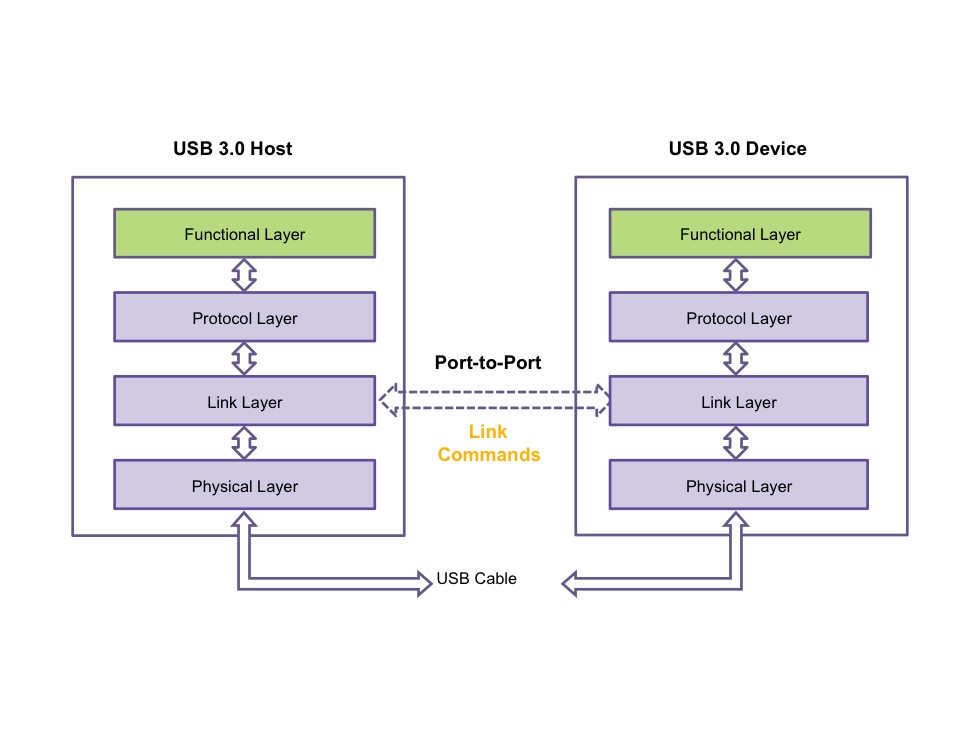
Figure 1 The Link Layer manages and controls the logical part of a Link (Source: Synopsys)
The functions of the Link Layer include:
- Link training, covering bit- and symbol-lock, and Rx equalization via TSEQ, TS1 and TS2 training order sets
- effective power management for four link power states
- handling low-frequency signaling for communications between two ports
- packet/link commands formation, including packet framing with K-symbols
- error handling of various types
The four low-power states of the Link layer are:
- U0, link active, the normal operational state
- U1, link idle – fast exit, in which the PLL remains on
- U2, link idle – slower exit, in which the PLL can be turned off
- U3, link suspend, in which the clock generation circuit can be turned off
The Link Layer also handles Header Packet Framing, by taking the 12 bytes of each Header Packet created by the Protocol Layer and framing them with eight more bytes of information. These include 4 bytes to indicate the start of the Header Packet and the end of the Packet Framing, 2 bytes of cyclic redundancy check (CRC), and a 2 byte Link Control Word.
Link Commands are used between two linked ports to communicate information between the upstream and the downstream port, ensuring link-level data integrity, flow control, and link power management. These commands are only sent from the transmitter link layer to receiver link layer, and are not routed onwards to other links.
A Link Command Word handles packet acknowledgement and error recovery, packet flow control, and link power management. The Command Word includes fields with which a receiving port can indicate whether the header packet is good, bad or should be retried. Other fields provide information about requests to change power status, and a ‘device present’ indicator.
Next => USB 3.0 Physical Layer
Further information
If you are new to designing with USB, or looking for tips on implementing USB 3.0 IP, attend Synopsys’ “USB 3.0 University.” Topics in this instructional video series range from fuller descriptions of the USB 3.0 Link Layer protocol, USB 3.0 link states, and USB 3.0 Link commands. Click on the links below.
USB 3.0 Protocol Layer – Part 1
USB 3.0 Protocol Layer – Part 2
