SystemC AMS—holistic analog, digital, hardware and software system-level modeling
One year after the publication of a draft, the analog and mixed-signal (AMS) extensions to SystemC AMS will be issued as a standard at the Design Automation and Test in Europe conference in Dresden in March 2010. At this point, SystemC/SystemC AMS will become the first ESL technology to cover continuous time modeling as well abstract digital hardware and software modeling.
Our world and the ways in which we interact with it are analog. Thus, more and more highly integrated systems contain analog components—the ITRS estimates that 80% of today’s system-on-chips (SoCs) are largely mixed-signal.
New technologies facilitate the integration of more and more features on one or more silicon die. At the same time, integrated systems have had to become more flexible to cover a wider range of use-cases, as heavily increasing design and production set-up costs have made highly targeted application-specific design more difficult to justify.
Analog circuits cannot be scaled as easily to the smaller lithographic dimensions of newer technologies as digital circuits. It is even more difficult to achieve the kind of configurability needed for one design to be ported to different application requirements. Because of those obstacles, the number and complexity of analog components are being reduced. The remaining analog functionality is then ‘assisted’ by digital components as much as possible. In this way, the performance and configurability of a typical analog front-end is increased through a tight interaction with a digital regulation and control subsystem. Sophisticated signal processing is then applied to compensate for intrinsic analog imperfections.
As we talk more and more about this idea of ‘digital-assisted analog’, a similar trend can be observed in overall systems. In automotive applications for example, more and more of the mechanical functionality is being either substituted or assisted by electronics. Consider the brushless motor—its mechanics are simple and therefore inexpensive, but it requires tightly coupled sophisticated electronics to function efficiently.
The consequence of these design trends is that it is getting harder and harder—in some cases, even impossible—to consider the analog components of a design independent of the digital ones or to design any IC without detailed knowledge of the full system environment. This is why executable and very broad-based system-level models have become essential to the design of an increasing number of SoCs.
SystemC is a C++-based hardware description language with the focus on system architecture design for large digital hardware and software systems. It is hosted and standardized (IEEE-1666) by the Open SystemC Initiative (OSCI), a not-for-profit organization composed of many leading semiconductor companies and EDA vendors. OSCI also provides proof-of-concept SystemC implementations on an open-source basis. As a result, most EDA vendors’ SystemC modeling and simulation environments are based on or derived from the OSCI implementation.
Because of the nature of C++, SystemC is very flexible and powerful. In particular, SystemC supports methodologies that allow engineers to describe the interaction of hardware and software via highly abstracted modeling that facilitates access to very high-performance system-level simulations.
Given the above-mentioned trends in design, the modeling and simulation of analog circuits, also at higher levels of abstraction, are both rapidly increasing in importance. So SystemC is being extended to the analog domain.
Following the SystemC philosophy, the SystemC AMS extensions focus on abstract modeling to deliver overall system-level simulations of ‘real-time’ application scenarios. This requires simulation performance several orders of magnitude higher than that achievable with models described in classical hardware description languages.
SystemC AMS introduces several abstract models of computation (MoCs) that promise to deliver such very fast simulation capacity. The restrictions implied by the abstract MoC usually do not limit system-level modeling. Indeed, the modeling of system-level behavior becomes much easier in many cases. Thus, the first version of the SystemC AMS standard includes support for timed data-flow, linear signal-flow and linear network modeling. These MoCs provide enough facilities to support abstract descriptions for a wide range of applications, especially for communication systems.
Brief overview of the SystemC AMS 1.0 language
The SystemC AMS extensions are fully compatible with the existing SystemC language standard. Thus, they do not impair SystemC and introduce no restrictions on the usage of already available language constructs. However, the newly introduced MoCs cannot be mapped directly to the generic MoCs of SystemC, because they are not based on a communication of processes. Instead, they describe equation systems.
Hence, each AMS primitive module contributes to an overall equation system, which has to be set up during elaboration and solved while simulating. The infrastructure of the SystemC AMS extensions must support these mechanisms.
The AMS language standard defines the execution semantics of the timed data-flow (TDF), linear signal-flow (LSF) and electrical linear network (ELN) MoCs, and gives an insight on the underlying enabling technology such as the linear solver, the scheduler and the synchronization layer.
The language is designed to be extensible. However, in the current standard, version 1.0, the interfaces to and class definitions of this enabling technology are left implementation-defined. The AMS designer can take advantage of dedicated classes and interfaces to create TDF, LSF, or ELN models by utilizing predefined modules, ports, terminals, signals and nodes.
Next to transient simulation in the time domain, the SystemC AMS standard defines means for small-signal modeling and for noise analysis in the frequency domain.
Timed data-flow
The TDF MoC is based on the well-known synchronous data-flow (SDF) modeling formalism. In SDF, a primitive module’s processing method is activated if enough samples are available at its inputs. If the processing method is activated, the input samples are read and the output samples are written. The number of samples read and written per activation is constant and already known before any simulation starts. That is why pre-scheduling during elaboration can be done, leading in turn to extremely fast execution during the simulation phase.
Unlike the untimed SDF model of computation, TDF is a discrete-time modeling style where data is considered as signals sampled in time. These signals are sampled at discrete points in time and may have discrete or continuous values, such as amplitudes. This time sampling allows the description of analog time-continuous behavior and an easy synchronization and communication with other time-driven MoCs.
The processing method of the model may contain arbitrary C++ code. Thus non-linearities can easily be modeled. For the description of analog dynamic behavior, special classes are provided that allow for the formulation of linear dynamic equations. These equations can be provided by classical linear transfer functions with numerators/ denumerators, by zeros and poles of operational amplifiers, or by state-space equations.
Figure 1 (p. 29) shows an example of a TDF model that represents an analog pre-filter with a switchable cut-off frequency and a voltage limitation at the out port. This example also demonstrates how a TDF module can communicate with SystemC’s discrete-event domain. The port sca_tdf::sc_in<bool> is a converter port that has to be connected to a SystemC signal of type sc_core::sc_signal<bool>. The port performs the required sampling and invokes the synchronization of the analog and digital time scales.
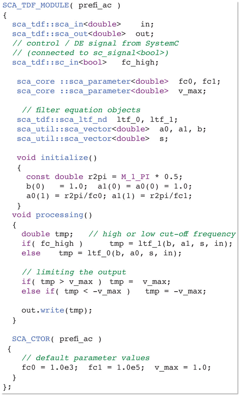
Figure 1
Example for a timed data-flow model. Source: Fraunhofer IIS/EAS
Linear signal-flow (LSF) and electrical linear networks (ELN)
Both models of computation consist of predefined elements. On the one hand, the LSF MoC defines non-conservative modules (connected by directed signals) like adders, multipliers, differentiators and integrators. On the other hand, the ELN MoC defines conservative electrical elements like resistors, capacitors and inductors.
In addition to these elements belonging to just one model of computation, several elements connecting two different domains are available. In LSF, for instance, there are multiplexers, demultiplexers and sources. In ELN, there are switches, voltage and current sources.
ELN and LSF models are composed within hierarchical modules in the normal SystemC way. An example of such a hierarchical SystemC description containing LSF elements is illustrated in Figure 2 (p. 29).

Figure 2
Hierarchical SystemC description. Source: Fraunhofer IIS/EAS
Modeling with multiple MoCs
Especially for system-level modeling of AMS systems, the usage of different MoC offers several advantages.
- Preset and widely adopted algorithms can be applied to many use cases and to represent certain properties within part of a system. This results in simulations that are orders of magnitude faster than those that use classical HDLs.
- The numerical solvability and convergence issues that occur when an analog part is modeled in too idealized a way can be reduced significantly.
- Because the different MoCs are well encapsulated, SystemC AMS models are very scalable—and so extremely large models are more manageable.
Figure 3 (p. 30) shows a simplified system view of a plain old telephone system (POTS) and illustrates the use of multiple MoCs within one system model. Such systems are responsible for the supply of an analog phone service, performing the voice processing and all signaling, as well as maintaining and testing the subscriber line.

Figure 3
System-level block diagram of a POTS system. Source: Fraunhofer IIS/EAS
These systems have to be highly configurable because they support a wide range of applications and local standards. They consist of an analog front-end (phone/protection circuit), a driver circuit (SLIC: subscriber line circuit), analog filters, analog-to-digital (ADC) and digital-to-analog (DAC) converters, digital hardware filters, a huge number of DSP algorithms and software to control the whole system.
Those system parts, whose signals can be considered as directed, are modeled in the TDF domain. These are the DSP algorithms, the digital hardware filters, the ADCs and DACs, and the analog filters up to the SLIC. The front-end and the environment are modeled by macro models in the conservative ELN domain. All control and software-related parts utilize the standard SystemC modeling features.
Figure 4 (p. 31) shows a typical system-level simulation scenario. It is a line diagnostic function for the measurement of the instantaneous capacitance of the ringer in the phone. Therefore, the software of the controller has to configure a lot of switches and registers throughout the whole system and has to react with respect to the instantaneous values of the line voltage and current. This example also shows that the real time to be simulated for this application scenario is in the range of seconds, whereby sampling times within the system are in the range of nanoseconds. This is a typical ratio for system-level investigations.
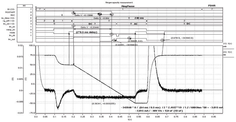
Figure 4
Example of a typical simulation scenario. Source: Fraunhofer IIS/EAS
Table 1 (p. 31) shows simulation times for a two-channel POTS system using different modeling and simulation technologies. Although the SystemC AMS model is less detailed, it covers all relevant functional effects and makes heavy use of SystemC AMS’ abstract MoC to speed-up the performance of the simulation.
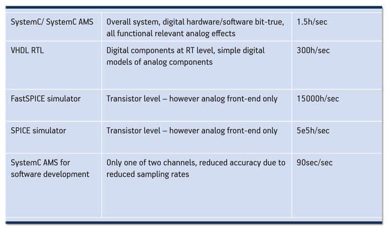
Table 1
Simulation times with models at different levels of abstraction. Source: Fraunhofer IIS/EAS
Nevertheless, SystemC/SystemC AMS simulations cannot supersede VHDL RTL or SPICE simulations because they do not represent the real implementation. However, the system model can be used to generate stimuli and as a golden reference for these simulations.
The last column of Table 1 shows how the simulation time can be decreased even more for certain use cases of the model. Here the flexibility of SystemC/SystemC AMS was used to derive a less accurate, but much faster model that meets the needs of embedded software development.
Table 1
Simulation times with models at different levels of abstraction. Source: Fraunhofer IIS/EAS
Ongoing developments
As already mentioned, the SystemC AMS language architecture was designed to be extensible. The current standard was heavily driven by communication applications. However, other application spaces—most notably automotive—increasingly need access to system-level techniques, particularly where there is a need to understand the interaction of heterogeneous analog components with software algorithms.
In contrast to communication applications, automotive must address strongly non-linear behavior at the front-end and back-end (e.g., driver stages with pulse width modulation or input characteristics of sensors). One example may be an airbag system where the squib driver is part of a non-linear control loop with a squib equivalent circuit.
Those parts of such systems that need highly detailed model descriptions are very small. Usually, there are just some devices at the front-end or back-end of the circuit. Those parts can easily be modeled with languages like Verilog-AMS or VHDL-AMS. However, those languages do not support modeling facilities at higher levels of abstraction like data-flow or transaction-level modeling (TLM).
As discussed before, these technologies are required to achieve the necessary simulation performance. Hence, OSCI has started work on how to introduce modeling capabilities similar to those in languages such as Verilog-AMS and VHDL-AMS. Bearing in mind that such non-linear parts are usually very small in a system-level context and independent from each other, they should not dominate the simulation performance.
In the automotive context, the world becomes heterogeneous. Engineers have to deal not only with electrical circuits, but also with other physical domains such as mechanics, magnetics and fluidics. Thus, concepts have to be developed that cope with several physical domains and quantities. Figure 5 shows an example of a simple DC motor that can be part of a complex window lifter system.

Figure 5
Example of a nonlinear description embracing multiple physical domains. Source: Fraunhofer IIS/EAS
Summary
With the publication of the SystemC AMS extensions standard in March 2010, the first standardized system-level language will be available that covers modeling of analog and mixed-signal behavior along with abstract digital hardware and software modeling. Consequently, system-level methodologies will take another step forward, reflecting how the systems themselves are becoming more and more heterogeneous and, above all, how interactions between different domains are becoming tighter and tighter. Nevertheless, the AMS standard is only a beginning. Further extensions are needed to support fast-growing application domains such as automotive.
Online
More information on SystemC, SystemC AMS extensions and other initiatives based around the language can be found online at:
- http://www.systemc.org/
- http://systemc-ams.eas.iis.fraunhofer.de/
Fraunhofer IIS/EAS
Zeunerstr. 38
01069 Dresden
Germany
T: +49 351 4640 712
W: http://www.eas.iis.fraunhofer.de/
