Staging virtual prototype bring-up for faster software development
How staging virtual prototype bring-up can accelerate the development of embedded software in complex systems.
The ability to develop and update embedded software quickly is becoming increasingly important to the success of SoCs. The most successful vendors in the mobile, consumer and automotive sectors have mastered both hardware and embedded-software development, so that they can quickly release and update well tested code that is optimized for power and performance.
This is difficult to achieve if hardware and software are developed independently until the integration and testing stages. Using early prototyping strategies, such as virtual prototyping, can help more closely align hardware and software development.
Virtual prototypes are simulation models of hardware written at a high enough level of abstraction that the software under development can be run and interactively debugged on the target hardware model without modifications. Of course, it takes time to develop virtual prototypes so it is important to achieve the right balance between their completeness (which enables them to run the same software as the target hardware), simplicity (to reduce the modeling effort) and debug utility (in terms of execution speed, visibility, determinism, etc.)
Tools such as Synopsys’ Virtualizer can help users create virtual prototypes of IP blocks, SoCs, devices or systems described as Transaction Level Models (TLM). Developers can combine existing TLM blocks with new models, verify the result as reflecting the functionality they are trying to achieve, and then export the outcome (including documentation, pre-configurations and examples) as a Virtualizer Development Kit (VDK) to be used for software integration, optimization and testing by software teams.
Building a virtual prototype
Since the goal of building a virtual prototype is to serve as a testbed for the software under development, it makes sense to ensure the virtual prototype is authored to serve the needs of software developers, while accurately reflecting the facilities and constraints of the hardware.
Hardware facilities may include memories, various forms of processor, peripherals accessed through registers, and interrupt schemes. Peripherals can also interact with each other through dedicated interface and control signals, for example DMA channels, and off-chip through standard interfaces such as Ethernet. Hardware components are often connected with each other through on-chip memory mapped busses.
The best source of the information necessary to create a virtual prototype is the technical reference manual (TRM) of the hardware platform. It usually includes the following elements.
A memory map, which describes the addresses at which every component of the SoC can be addressed by the processor. The memory map is used by build tools, such as the linker, so it knows where to put each part of the binary software (such as the instructions, data, heap, stack, etc.). The memory map is also used by the lowest software layers, such as drivers, to interface with the on-chip hardware peripherals.
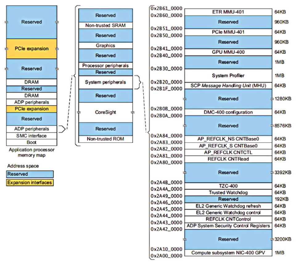
Figure 1 Partial memory map description in the Juno ARM Development Platform SoC reference manual (Source: Synopsys)
Interrupt tables list the logical mapping between every possible interrupt on the system, be it created by hardware or software, and an interrupt service routine. Hardware interrupt signals are typically connected to one (or more) interrupt controllers, which connect in turn to the processor.
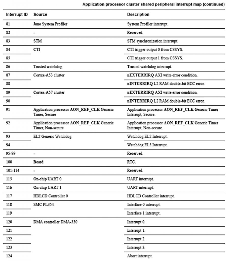
Figure 2 The interrupt table on the Juno ARM Development Platform SoC from the TRM.
Clock, reset and voltage-tree information is provided so that these elements of the hardware can be controlled dynamically by software through dedicated peripherals and/or external ICs. This code has to be right, or it can cause unpredictable performance and damage the hardware.
A list of supported off-chip interfaces, such as Ethernet and USB, and details of the on-chip peripherals that control those interfaces.
Control interfaces, to drive external components such as DMA controllers or simply to provide dedicated signals between components.
A TRM will also provide information about the SoC’s peripherals, in terms of:
- Interface configuration, such as clock and reset inputs, interrupt outputs, bus ports, external (off-chip) pins, and any other side-band signals.
- Memory-mapped registers, providing information for every register about its name, relative address (offset), read/ write permissions, size, etc. Register descriptions usually include all the bitfields each register contains, with a name for each bitfield, its name, position and size, specific permissions etc.
TRMs will often also include a description of the functionality of each pin interface, register and bitfield, and the behavior that is triggered on the peripheral. The TRM may also describe the functionality in terms of modes of operation and configuration procedures.
This information enables developers to start creating a virtual prototype that represents the functionality of the hardware target accurately, so that the embedded software under development can run as well on the real hardware as on the model.
Co-developing a virtual prototype and the target code
Virtual prototypes are most valuable when they are available at the earliest stages of development. To make this possible, it makes sense not to wait for the complete virtual prototype to be available, but instead to work with what you have and evolve the target software in step with its development.
Given that the software stack will be developed by several teams, each handling a separate part such as writing the bootloader or porting the operating system, or focusing on the integration of those parts, it makes sense to develop the virtual prototype’s capabilities in step with this.
For example, the first version of the virtual prototype may only include the small subset of components needed to enable work on the bootloader software. Another version may be focused on a particular hardware abstraction layer, to enable driver development. Eventually the virtual prototype should evolve to the point where it represents the complete hardware – and can run the full software stack being developed for that hardware.
One of the challenges (and benefits) in developing a virtual prototype is that the process relies on strong communications with both the hardware and the software teams, so the virtual prototype developers can know what each team is trying to achieve, their schedules for each milestone, and the dependencies between the two. This can be a challenge since hardware and software teams rarely work in a fully synchronized manner. However, the development of a virtual prototype can act as an executable specification of the hardware, enabling closer integration of the two teams’ work.
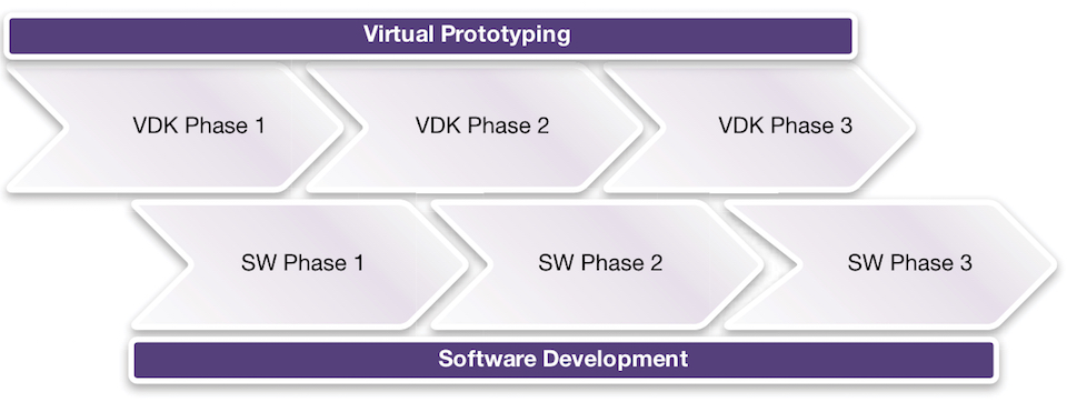
Figure 3 Staging the VDK development according to the software development phases (Source: Synopsys)
How Virtualizer Studio can help create virtual prototypes
Virtualizer Studio can be used to develop virtual prototypes and VDKs. It helps with three key tasks:
TLM creation
This part of the tool addresses the development and test of TLM components, mainly peripheral types. Information can be entered manually or imported from sources such as IP-XACT models or Excel spreadsheets, and the tool will then generate a SystemC/TLM skeleton of the peripheral model. This skeleton contains the interfaces, registers and bitfields, as well as placeholders for entering the behaviour of each element. This skeleton can often account for half of the total lines of code in the model.
The tool also has unit test creation and execution, functional coverage and code coverage capabilities to test the model as they fill out the skeleton. It sis possible to enter designs, generate and edit code, build, test, debug, and export models from within the same environment.
VDK creation
The tool can help users assemble building blocks, of varying complexities, ranging from a single component to a complete subsystem, into platforms. The building blocks can contain extra information alongside the TLM, which the tool can use to help it during the assembly process. It also helps Virtualizer Studio automatically deal with SystemC/TLM implementation details such as inserting any adaptors, transactors, or inverters, necessary to connect the blocks.
The tool can also work with placeholders, so development isn’t held up waiting for a particular building block to become available. Models created or imported through the TLM Creation facility can be easily instantiated into those placeholders. Virtualizer Studio also offers Connectivity Tables, in which users can specify how building blocks should be connected. The tool also offers ‘worked examples’, or ‘connectivity planes’ for memory maps, interrupts, clock, voltage and reset trees, DMA channels, off-chip interfaces etc., as well as configurable starting points for entire virtual prototypes.
This can save a lot of work. It is possible to generate, configure and connect an ARMv8 based multi-cluster subsystem, typically including an application processor, cache-coherent interconnects and global interrupt controller, in a few clicks.
VDK debug
Debug within Virtualizer Studio can be used during model creation or platform authoring to debug any component at the SystemC/TLM level. The integrated source code debugger has SystemC aware views (of language features such as threads and events) to make it easier to track and fix any model bugs.
The tool can also be used as a virtual logic analyzer, displaying difficult-to-reach hardware details such as internal interfaces, registers, bitfields, and model state. Breakpoints can be added to any virtual hardware element, which give better control of system execution than a software debugger.
Root-cause analysis is supported by the ability to trace and correlate the software’s execution on the processor with hardware events occurring on the platform. The hardware models can also tell the user when an error or warning has occurred.
Virtualizer Studio is based on the Eclipse integrated development environment (IDE)and so allows easy integration of third-party plugins such as version control and team synchronization tools. It can also integrate with build-chain and software debugger plugins to enable the compilation and debugging of the software source code from within the same IDE.
Refining a VDK
Once a VDK has been created, the user can start refining any placeholder building blocks by creating a TLM model for each of them. For example, through the TLM Creation functions of the Virtualizer Studio, it is possible to import the full interface and register definition of an IP block and then create a skeleton TLM that contains all the interfaces, registers and bitfields it uses to interact with the rest of the system. Any modifications to the TLM model will be automatically reflected at the VDK level. This approach means that a TLM can be integrated into the VDK while at the same time, the IP block it represents continues to be tested and refined.
Author
Victor Reyes is a technical marketing manager in the Virtual Prototyping group at Synopsys. His responsibilities are in the area of virtual prototyping technology and tools with special focus on Automotive. Reyes received his MsC and PhD in electronics and telecommunication from University of Las Palmas, Spain, in 2002 and 2008, respectively. Before joining Synopsys, he held positions at CoWare, NXP Semiconductors and Philips Research.
