Real datatypes and tools enable fast mixed-signal simulation
Wreal modeling brings fast methods for simulating mixed-signal designs into the digital environment. And tools have arrived that make it easier to incorporate existing analog IP.
Today’s system-on-chip (SoC) designs integrate an unprecedented number of functional blocks and incorporate a rapidly increasing number of analog and mixed-signal functions, from PLLs and power functions, for local clock and power control, through ADCs and DACs for real-world interfaces to custom, digitally enhanced mixed-signal cores for handling RF and high-speed communications.
The key issue for the team charged with verifying the functionality of these large SoCs is one of performance. With digitally assisted analog, there are complex interactions between the domains that need to be tested under many different conditions. In an ideal world we would be able to mix digital logic with analog circuitry modeled to SPICE levels of accuracy and expect an answer quickly. In reality, it can take days to complete a mixed-signal simulation using SPICE-level accuracy for even a comparatively low number of digital clock cycles, such as an analysis of the performance of a 16bit ADC over its full range of sample values to see how the control logic behaves.
At each step, the analog engine needs to solve a set of simultaneous equations that model the continuous-time behavior of the analog circuitry. Until that is completed, the digital simulator has to wait before it can move onto the next clock cycle.
Speed up mixed-signal simulation
One option is to move as much of the analog simulation as possible into the domain of the cycle-based solver, which provides a speedup as shown in Figure 1. Bringing analog-focused data types into simulation was made possible through dedicated mixed-signal simulators.
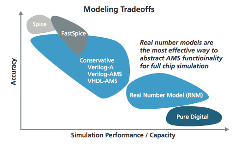
Figure 1 Speed and accuracy tradeoffs of mixed-signal modeling methods
The 2012 update to the SystemVerilog Language Reference Manual (LRM) introduced support for real-number modeling, adding advanced functions designed to streamline the simulation of mixed-signal functions. As with the ‘real’ signal in VHDL or the ‘wreal’ type in Verilog-AMS, real-number types in SystemVerilog are discrete-time, data-sampled floating-point numbers that can be used to approximate continuous-time signals in analog.
The discrete-time nature of the real-number variables means that modeling needs to be performed in a different way to continuous-time approaches. For example, modeling the precise behavior of the negative-feedback loop inside an op-amp is likely to be inaccurate for high slew rates. However, the focus of real-number modeling is on behavior – the op-amp will probably form the heart of an amplifier circuit. That circuit’s behavior could be represented as a transfer function using discrete, sampled values that may be derived from simulations performed using SPICE or a tool such as Spectre AMS.
The key benefit of the discrete-time, digital-solver method is speed at a level of accuracy that allows digital functionality around the mixed-signal blocks to be tested extensively. One customer [Texas Instruments] has used real-number modeling to prove the performance of a 14bit ADC and DAC pairing. To simulate the design, which encodes 16,384 different digital output or input states, respectively, a conventional mixed-signal simulation took three days. A model of the analog section modeled using real-number values took three seconds to execute, allowing much more extensive simulation of the digital control circuitry used to interface to the ADC and DAC.
SystemVerilog extensions for wreals
The real-number modeling support in SystemVerilog goes beyond simply providing a simple variable type. The 2012 edition of the LRM introduces two extensions that improve verification engineers’ ability to model mixed-signal designs in a way that reflects real-world situations. Two of the most important additions, for which support is now included in simulators such as Incisive, are user-defined types (UDTs) and user-defined resolution (UDR) functions.
UDTs were introduced to support nets with more than one real value. This can be used to allow a net to carry information about both voltage and current simultaneously, avoiding the need to use additional variables to encode additional data and making the resulting code clearer and easier to maintain as all the properties for a given net are held in one nettype variable. Each nettype takes the form of a C/C++ struct.
SystemVerilog 1800-2012 also addresses the case when multiple drivers are present. UDR functions determine what the sampled value of the net should be at a given time, allowing for the resolution of multiple-driver situations. In simulators such as Incisive, built-in functions can be used to determine, for example, the output of a net with multiple drivers. Or the designer can opt to create a custom function that is associated with a given nettype through a SystemVerilog declaration, as shown in Figure 2.
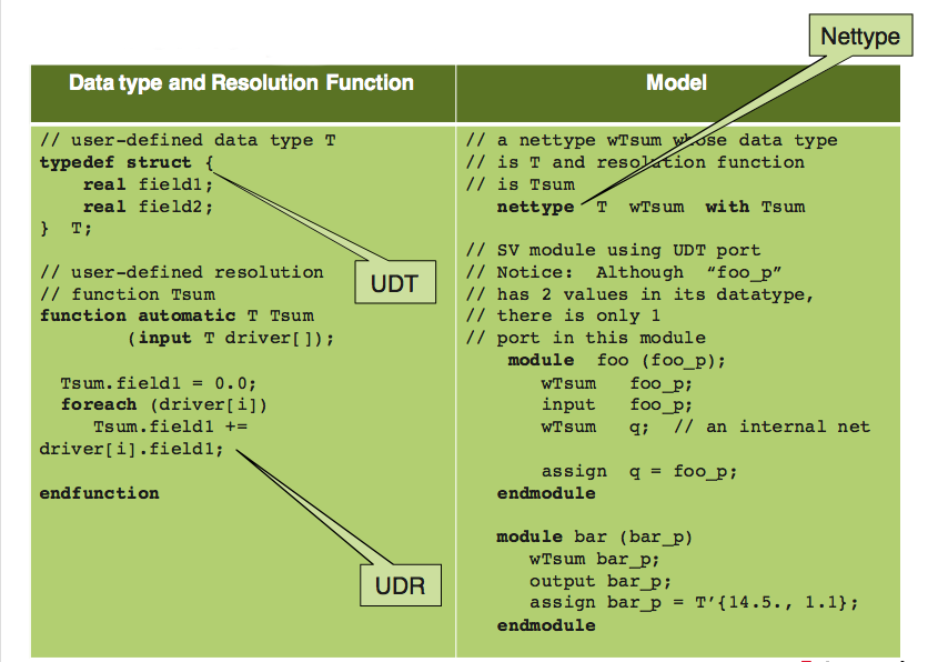
Figure 2 Usage of custom signal resolution functions using a nettype
Once in the SystemVerilog domain, models of mixed-signal systems and subsystems can take advantage of the verification infrastructure that already exists. For example, assertions can be employed to perform checks on signal ranges and other conditions to ensure that the analog IP is not used outside of its specified range. This helps prevent situations arising where the model appears to simulate correctly but SPICE fails because the model or the core itself is used outside its approved range but does not appear to fail during behavioral simulation. Furthermore, assertions help ensure that the IP and surrounding logic adhere to the original specification as defined using assertions.
An issue with any form of behavioral modeling is timely access to accurate representations of the IP that will go into the final SoC. Generating the models from scratch in SystemVerilog code takes time and requires the attention of analog designers who have limited, if any, experience with the language but who can implement a schematic very easily. To help bring real-number models into the SystemVerilog domain, Cadence developed the Schematic Model Generator (SMG).
Model generation
Rather than convert existing schematics – which will often include low-level analog feedback loops that do not map well into the discrete-time domain – the SMG is designed to allow the easy capture of analog functions in schematic form at a higher level, using blocks to represent functions such as amplification, digital to analog conversion and transfer functions. Calibration blocks that link to table lookups allow the easy of nonlinearities and also to provide a way to reuse common blocks in different designs that may be tweaked for each instance by the custom-circuit design team. Calibration data can easily be updated during the progress of the design to reflect the actual performance of the analog IP based on SPICE simulation using foundry models or the results of test chips.
Assertions and verification blocks can be added to the SMG-built models to allow easy measurement of parameters during simulation and to check usage across different designs.
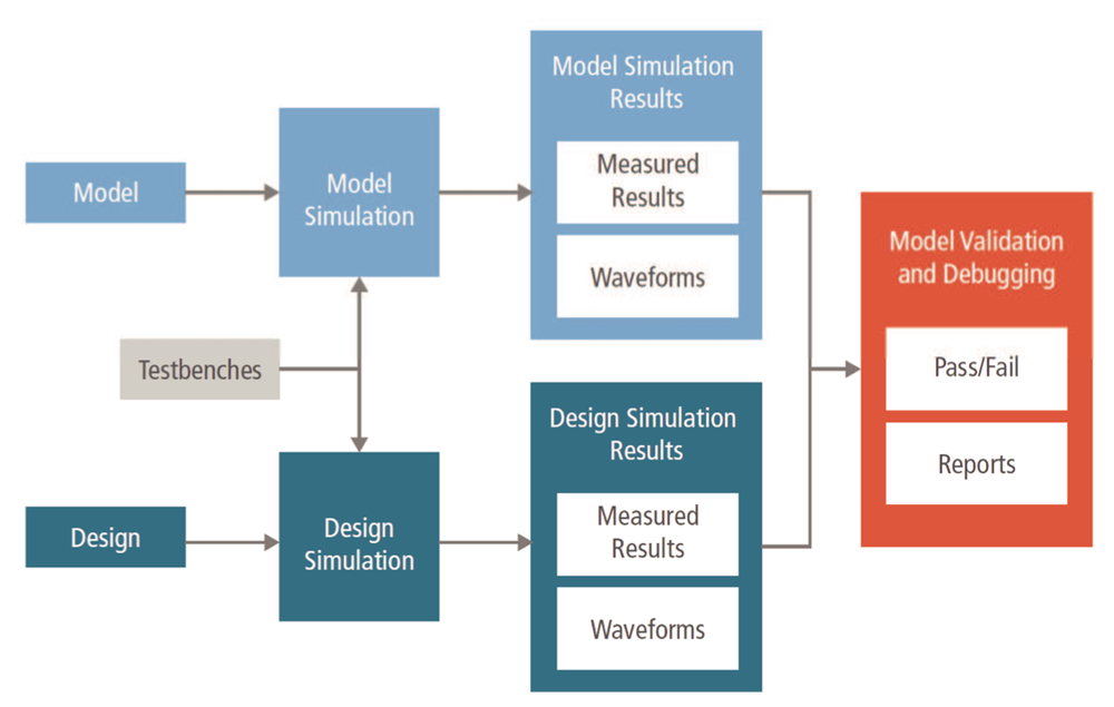
Figure 3 The model-validation flow
To ensure a close correlation between the behavioral model and the original analog or mixed-signal IP, the amsDMV tool performs validation of the signals generated by the model against high-accuracy simulations of the reference design. Manual waveform comparison/debugging in the analog domain often leads to complex and incomplete answers. Although this provides useful information for a discussion, it is not useful for a regression-based methodology. So, amsDmv provides a clear answer as to whether the behavioral model has passed the validation process. If it fails, the problematic parts of the simulation can be highlighted to an analog designer to determine how best to fix the behavioral model. The model-validation flow is shown in Figure 3.
As SoCs become more complex and incorporate increasing amounts of analog and mixed-signal functionality, real-number modeling provides a way to streamline simulation-based verification. Support for advanced real-number modeling techniques through advanced data types as well as support tools for model creation allow easier integration of this technique into the verification flow.
Author
Pete Hardee is director of product management in the Cadence Incisive team, with responsibility for Incisive formal and digital mixed-signal products.
Company info
2655 Seely Avenue
San Jose, CA 95134
(408) 943 1234
www.cadence.com
