Product development efficiency through ECAD-MCAD collaboration
In May 2008, the ProSTEP iViP Association released an agreed data schema and communication protocol to enhance collaboration between electrical and mechanical CAD tools (ProSTEP iViP Recommendation ECAD/MCAD, PSI 5).
The article sets out the need for the new standards and how they deliver greater design effi ciencies than existing technologies, such as the IDF data transfer format.
It also describes PSI 5’s initial implementation in tools from Mentor Graphics and Parametric Technologies that are already available to users.
A methodology is then described for a typical collaboration between electrical and mechanical engineering across the development and refi nement of a printed circuit board design.
Electronics companies are under increasing pressure. Today’s market demands that they reduce development costs, speed time-to-market, and deliver more competitive products. Meeting these goals requires enhancements to design tools and processes, as well as increased efficiency within – and between – all enterprise organizations involved in the design and manufacture of an end-product.
Incremental improvements to design tools and processes are necessary, but often insuffi cient themselves in enabling companies to reach aggressive business goals. Rather, quantum improvements are required that, with a single change, signifi cantly improve the concept-to-delivery process. So, what are we talking about here? One example of this kind of broadly effective change is the implementation of more effi cient collaboration, turning serial processes into parallel ones, changing paper communication to electronic, and enabling multiple organizations in an enterprise to break down internal barriers and negotiate a proposed design change in real time.
Most major electronics companies have separate electrical (ECAD) and mechanical (MCAD) design organizations. Ensuring close collaboration between these teams throughout a product’s design process can signifi cantly reduce cycle times, lower the risk of re-spins, and improve quality.
The framework for change
The fi rst obstacle to creating an effective collaborative framework between your ECAD and MCAD operations is that they use sophisticated design solutions that do not speak the same language. Tools and methodologies have evolved separately in the two domains during the last 40 years to optimize designer productivity and meet customer requirements.

The result is that the ECAD and MCAD worlds have databases and constructs that are very specifi cally tuned. When you attempt to transfer data back and forth between them, it is like trying to communicate in two completely different languages (words, constructs, subtleties) that have only a little in common. The next challenge, then, is to enable collaboration in a way that represents information in a form familiar to the users. Forcing ECAD and MCAD designers – designers who are already well trained in the existing tool infrastructure – to adopt new, unfamiliar GUIs and different languages just to use collaboration tools will signifi cantly increase the training required and thus reduce the adoption rate. Only widespread use will produce the desired rise in productivity.
Legacy limitations
A data interface between ECAD and MCAD has existed for a number of years. This industry standard format, IDF, was typically used to import the board outline, mounting holes, and other mechanical parameters into the PCB database at the beginning of the board-level design process. At the end of the PCB design process, it was used to interface the PCB database (component placements, etc.) back to the mechanical tool. Whenever parties communicate and exchange data based on reaching a common goal, some form of collaboration takes place even if it is not a particularly effi cient one. In the case of IDF, the format was designed and effectively used as a data dump. But it had no way of identifying the incremental changes that had occurred in either the PCB or the enclosure design. So, at a more ‘useful’ level, collaboration still consisted of notes scribbled on pieces of paper and verbal communication between the disciplines. It was not only time-consuming but also very error-prone.
In addition to an ECAD-MCAD data transfer mechanism, many ECAD solutions incorporate 3D viewers. The engineer can even insert the board and view it in an enclosure supplied by the mechanical system. Such communication can be considered collaborative, and is more effective than the mass exchange of data under IDF, but there is still considerable room for improvement.
Yes, it gives the PCB designer the opportunity to try and spot obvious errors (e.g., gross PCB interference with the enclosure). But it does not provide an opportunity for realtime communication and incremental data transfer between the disciplines that are required to properly negotiate the resolution of any problems.
Specifying a standard
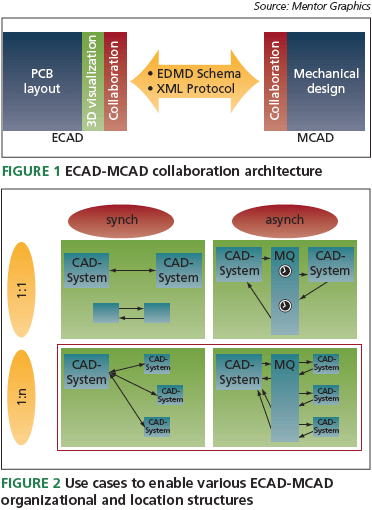
Given this backdrop, 2005 saw Mentor Graphics partner with some mechanical solution suppliers, mutual customers, and the ProSTEP iVIP Association in the development of some formal ECAD-MCAD collaboration capabilities. The first step was to solve the ECAD-MCAD language problem. Rather than attempting to completely change the basic data models in both domains, the partners identifi ed and prioritized a subset of those objects most likely to be changed during concurrent design of the enclosure and the PCB (e.g., mounting holes, board outline, component placements, height restrictions, etc.). Each object’s names, properties, and constructs were specifi ed in a mutually agreed form so that both domains could fully understand them.
The resulting Electrical Design-Mechanical Design (EDMD) schema was the first true interchange format to represent incremental changes to a design that both domains could view, and also test and update in their respective databases. These were the beginnings of a common language covering the most important collaboration objects.

The partners also agreed on XML as the collaboration interaction protocol, the standard use cases that were to be provided, and the relationship of the collaboration tools with native ECAD and MCAD tools. This was then specifi ed in a document and approved in spring 2008 as a ‘go forward standard’ (ProSTEP iViP Recommendation ECAD/ MCAD, PSI 5), open to all ECAD and MCAD suppliers. Delivering the standard
Two suppliers, Parametric Technology Corporation (PTC) and Mentor Graphics, have developed and delivered the fi rst ECAD-MCAD collaboration capabilities in line with the specifi cation. Their tools address collaboration objects assessed by the partners as having the highest priority: use cases and domain-friendly designer interaction.
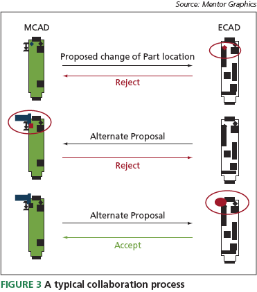
Given the global nature of electronics design, collaborative environments must enable not only real-time interactions but also address the fact that the ECAD and MCAD organizations might be geographically dispersed across multiple time zones. Consequently, one of the use cases addresses both synchronous and asynchronous design. During synchronous collaboration, it is assumed that both designers are online and can immediately respond to change proposals. For asynchronous collaboration, the changes must be stored persistently and presented to the collaboration module at the appropriate time. A typical use case must allow for one-to-one collaboration as well as one-to-several, and several-to-several. Some of these scenarios are shown in Figure 2.
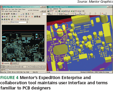
Collaboration is typically not an event but a process. Seldom does a designer propose a change that is accepted outright. More often, a change is proposed and either rejected outright by the other domain or a counterproposal made, beginning a negotiation process. To facilitate this process, the collaboration tools need to have the capability to ‘sandbox’ proposals and implement only the result of the completed negotiation in the permanent design database. Here is a typical collaboration process (also summarized in Figure 3):
- The ECAD designer needs to change the location of a component. The proposed change is made in a sandbox mode using the collaboration tools and the data is sent to the MCAD designer.
- The MCAD designer receives the proposed change through the collaboration tool and, in the MCAD sandbox, begins to test the effects of the proposal.
- The MCAD designer determines that the proposed change will not fi t properly into the enclosure in its current form and rejects the proposal. The MCAD designer, via the collaboration tool, then proposes an alternate change that will meet mechanical constraints.
- This counterproposal is received by the ECAD designer who tests it in the PCB layout sandbox and accepts the counter proposal.
- Now accepted by both domains, the counterproposal is then inserted into the mutual master databases of both the electrical and mechanical systems. · The change is versioned and time stamped.
Another positive feature of the collaboration tools created by PTC and Mentor is that each maintains interface characteristics that are similar to those in the already available software for each domain. Graphics, options, and menus use terms familiar terms from other tools so users do not have to learn entire new languages or interfaces to be profi cient. For example, Figure 4 shows how one collaboration tool retains a similar appearance and framework to Mentor’s Expedition Enterprise software. Retaining such familiarity will improve the adoption rate of the process and accelerate the flow of benefits to the electronics industry.

Reaping the benefits
True collaboration between all disciplines involved during the product development process can signifi cantly improve an electronics company’s efficiency and designer productivity. As outlined in this article, capabilities developed jointly by Mentor Graphics and PTC now exist that enable collaboration between electronic and mechanical designers.
These capabilities provide for the communication of incremental proposed changes to either the mechanical or electrical design followed by real-time negotiation through a new industry standard data format and communication protocol. We believe that other ECAD and MCAD suppliers will rapidly adopt this open standard, thus benefi ting the entire electronics industry.
Notes
ProSTEP iViP Recommendation ECAD/MCAD, PSI 5 is available to download at http://www.prostep.org/en/download-area/ recommendations-standards.html in Adobe Acrobat format. Go to the page’s ProSTEP iViP subsection.
Mentor Graphics
Corporate Offi ce
8005 SW Boeckman Rd
Wilsonville
OR 97070
USA
T: +1 800 547 3000
W: www.mentor.com


