How place and route is adapting to challenges below 10nm
Multi-patterning, finFETs and more are forcing more detailed overhauls of P&R software at each process node. We dig into some of the key new issues and how they are being addressed.
Place and route software must today undergo extensive updates for each new process node, starting early in the foundry’s technology development cycle. Updates have traditionally concentrated on upgrading the router and DRC checker to handle new, more complex routing rules. But with the introduction of multi-patterning and FinFETs, new types of constraint (e.g., implant (submetal) rules) have begun to have a direct impact on other place and route engines.
As a result, software changes for advanced nodes must now address all parts of the place and route software. This is especially true for 10nm and below.
Let’s look at the nature of the new constraints and how they illustrate the ways in which physical design tools must adapt?
We begin with violations that emerge immediately after placement and legalization. These fall into two main categories.
- DRC errors on submetal layers, such as implants, including:
- Width, spacing, and area DRC on implant layers;
- Jog rules, typically on the oxide diffusion (transistor active area) layer; and
- Prohibited drain-drain.
- Problems on metal and via layers, including:
- Direct DRC violations, such as same mask spacing, between ports or blockages of adjacent library cells;
- Violations between library cell ports or blockages and preroutes, such as wires and vias in the power/ground grid;
- Unroutable cell ports; and
- Pin alignment and track color matching.
Submetal rules: width, spacing, and area
In a basic scenario, standard cells contain just two shapes on submetal layers. These typically divide the cell in half vertically: one half is the N-implanted area, and the other is the P-implanted area. These shapes are usually expressed in LEF files as blockages and are often called implant layers. If such a submetal shape is too small then it must be flagged as a DRC violation, as shown in Figure 1.
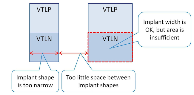
Figure 1. The placement engine should distinguish which violations are repairable with filler insertion and which require cell movement (Mentor Graphics)
Submetal rules: oxide diffusion jogs
Two new types of submetal rule were added during the introduction of 16/14nm technology: minimum-jog (aka min-jog) and drain-drain abutment. Min-jog violations usually apply to the oxide diffusion (OD) layer (an example is shown in Figure 2).
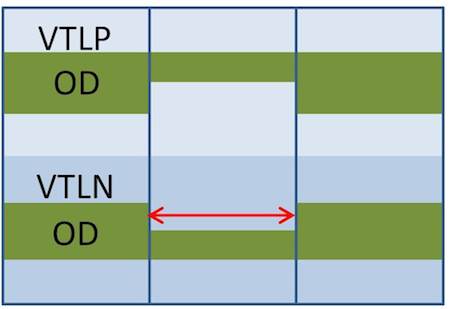
Figure 2. The horizontal OD edge is too short, so this is a min-jog violation (Mentor Graphics)
A min-jog violation can be fixed by the placement engine by inserting a matching cell to the cell in the middle or inserting a gap that will be filled later (Figure 3). Tools need to be able to undertake these kinds of task.
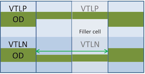
Figure 3. The placer inserts a matching cell to fix a min-jog violation (Mentor Graphics).
Metal and via layer rules: pin access and direct DRC with preroutes
Pin-access problems are not new but they are becoming more common. Figure 4 shows a cut-spacing violation. The placer should avoid this violation without running a full DRC during every cell move.
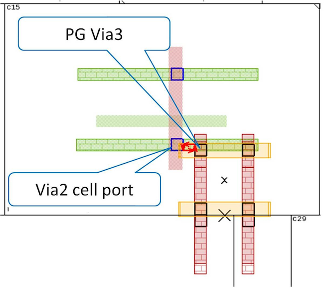
Figure 4. A cut-spacing violation between a cell blockage and power/ground (Mentor Graphics)
Abutted cells can also cause pin blockages, but you do not want to deploy a blanket prohibition on abutment between all cluster members. Today’s more advanced place and route tools therefore take a statistical/analytical approach and use soft constraints to improve routability.
Metal and via layer rules: pin-to-track color matching
Pin-to-track color matching is a new placement constraint at 10nm. It has been made necessary by the introduction of self-aligned double patterning. It has a direct impact on cell placement because the cell ports must be centered on a routing track and the mask and track colors must match. Routing pitch is not always equal to 2X site width, so a cell can easily land in locations where ports will either miss the track or will be on the opposite color. Examples of a pin-to-track color violation are shown in Figure 5.
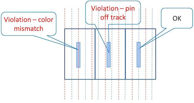
Figure 5. Pins off track and pins mismatched to the track color can emerge with self-aligned double patterning (Mentor Graphics)
A 10nm-ready placer will figure out the discrete subset of legal locations for each library cell that guarantee alignment and mask matching between cell ports and routing tracks.
Technologies with triple-patterned M1 require the same mask M1 spacing to be very large. A strategy based on both spreading cells and designing cells to prevent triple-pattern conflicts will prove too conservative. Instead, it makes sense to use a hybrid approach based on swapping masks wherever possible. This means that the placer will replace a cell with its ‘mirror’ variant, where M1 mask1 shapes become mask2 and vice versa. Because this does not entail any actual cell movement, it has no impact on routability or timing. Only those violations that cannot be cured with mask swapping are repaired with spreading.
Place and route tools in practice
This article has described the new constraints at 10nm and below that affect the digital implementation flow. These new constraints cannot be ignored during global placement, optimization, and clock tree synthesis. Your place and route system must fully understand the related rules and help deliver a clean and routable placement without adding to runtime. There are ways to do this, mostly through abstraction. But abstraction can lead to inaccuracies, so it requires a careful calibration of techniques.
To read a more detailed description of the new constraints, how they affect various place and route engines, and how they are addressed by the strategy used by Mentor Graphics place and route tools, download the new whitepaper: Understanding Physical Design Constraints in the 10nm Era
About the authors
Benny Winefeld is a product engineering for the place and route tools at Mentor Graphics. Sudhakar Jilla is the director of marketing for the IC design division at Mentor.
