Modeling embedded systems using SystemC extensions
SystemC AMS extensions introduce new language constructs for the design of embedded analog/mixed-signal systems. This paper presents the novel modeling language for analog and mixed-signal functions that supports design and modeling of telecommunications, automotive and imaging sensor applications at various levels of abstraction. A simple example illustrates how new features facilitate a design refinement methodology for functional modeling, architecture exploration and virtual prototyping of embedded analog and mixed-signal systems.
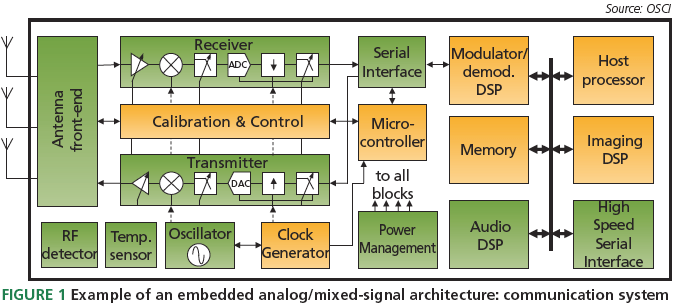
There is a trend toward tighter interaction between embedded hardware/software (HW/SW) systems and their analog physical environment. This leads to systems in which digital HW/SW is functionally interwoven with analog and mixed-signal (AMS) blocks, as shown the communication system in Figure 1. Examples of these embedded analog/ mixed signal (E-AMS) systems include cognitive radios, sensor networks and systems for image sensing. A challenge to their development involves understanding the interaction between HW/SW and AMS subsystems at the architectural level. This requires some means of modeling and simulating these interacting systems.

SystemC supports the refi nement of HW/SW systems to RTL by providing a discrete-event (DE) simulation framework. A methodology for the generalized modeling of communication and synchronization that builds on this framework is available using transaction level modeling (TLM) techniques. However, the SystemC simulation kernel has not been designed for the modeling and simulation of analog, continuous-time systems and lacks a refi nement methodology that describes analog behavior from the functional level down to the implementation level.
System-level tools are often used for functional modeling and simulation. They may capture continuous-time behavior, but they do not target the design of E-AMS systems at the architectural level. Hardware description languages (HDLs) such as VHDL-AMS and Verilog-AMS target the design of mixed-signal subsystems close to the implementation level, but have limited capabilities regarding HW/SW co-design at high levels of abstraction. Existing cosimulation solutions mixing SystemC and Verilog/VHDLAMS do not provide high enough simulation performance and lack a seamless design refi nement flow for modeling mixed discrete-event/continuous-time systems and HW/ SW systems at the architectural level.
In response to demand from the telecoms, automotive, and semiconductor industries, SystemC AMS extensions are being introduced, providing a uniform and standardized methodology for modeling E-AMS systems. This paper gives an overview of those extensions.
Use cases and requirements
The SystemC AMS extensions are designed to enhance the HW/SW-oriented SystemC class library by providing a framework for the functional modeling, architectural exploration, integration validation, and virtual prototyping of E-AMS systems. Such use cases require a means for modeling and simulation that is more abstract than is available from existing HDLs. At the same time, designers should be able to model AMS components and their interactions with HW/SW systems. The extensions provide a standardized formalism for the modeling of AMS architectures that bridges the gap between functional modeling frameworks and the HDLs used for implementation.
To that end, we consider the following modeling formalisms:
Signal flow models describe AMS systems (such as control systems or fi lter structures) at the functional and architecture levels using block diagrams, assuming continuous time and directed real-valued signals. For simulation, differential and algebraic equations are solved numerically at appropriate time steps. Therefore, simulation of signal flow models is often a time-consuming task. Data flow models are common for modeling DSP algorithms and communication systems at the functional and architecture levels by processes that communicate via buffers. For simulation, the processes are activated in the data flow’s direction, considering different data rates. Note that, in general, data flow models are untimed and can have different semantics. When modeling AMS systems, timed semantics are introduced by assuming discrete time steps between data tokens. Although not as accurate as a continuous-time signal flow, a discrete-time data flow provides a higher simulation performance with reasonable accuracy.
Electrical networks are essential for modeling E-AMS systems. They are required to model loads, protection circuits, and buses at high frequencies using macro models for describing continuous-time relations between voltages and currents. For simulation, differential and algebraic equations are solved, but efficiency can be maintained by using only linear primitives and switches. Figure 2 gives an overview of modeling formalisms that are required for designing AMS systems and their use cases between the functional level and implementation.

A major requirement is to maintain an acceptable simulation performance while modeling the architecture’s behavior with suffi cient accuracy. Therefore, the AMS extensions must enable the use of dedicated simulation kernels synchronized with the standard SystemC kernel.

Electrical networks require specific simulation capabilities. The simulation of such models needs structural analysis, the setup of differential and algebraic equations (DAE), and numerical methods for solving them.
Furthermore, the AMS language must enable the use of dedicated simulation kernels for special cases such as linear networks, which permit a signifi cantly higher simulation performance compared with nonlinear networks. For models, the special case of synchronous data flow allows the implementation of a dedicated simulation kernel that provides considerable speed-up compared with the SystemC kernel.
Another important requirement is extensibility. Industrial design flows for E-AMS systems use SPICE-like circuit simulators with high accuracy, special support for RF, nonlinear systems or other application-specifi c extensions. Therefore, the SystemC AMS extensions should allow the industry or EDA vendors to integrate ‘user-defi ned extensions’ to support different domains.
Language structure and use cases
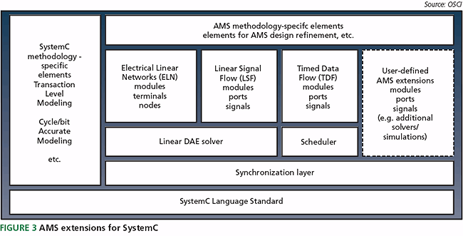
The SystemC AMS extensions meet the requirements and use cases discussed in the previous section. They provide support for signal flow, data flow, and electrical networks. The extensions are fully compatible with the SystemC standard as shown in Figure 3. Electrical networks and signal flow models use a linear DAE solver that solves the equation system and is synchronized with the SystemC kernel. The use of this solver restricts networks and signal flow components to linear models to provide high simulation performance. Data flow simulation is accelerated using static scheduling that is computed before simulation starts. This schedule is activated in discrete time steps, where synchronization with the SystemC kernel introduces timed semantics. We therefore call it a ‘timed data flow’ (TDF). The SystemC AMS extensions define new language constructs identified by the prefix ‘sca_’. They are declared in dedicated namespaces ‘sca_tdf’ (timed data flow), ‘sca_eln’ (electrical linear networks), and ‘sca_ lsf’ (linear signal flow) according to the underlying semantics.
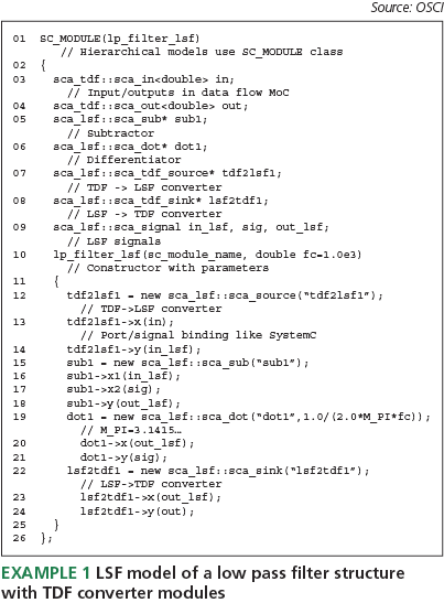
By using namespaces, similar primitives as in SystemC are defined to denote ports, interfaces, signals, and modules. For example, a TDF input port is an object of class ‘sca_tdf::sca_in<type>’. Linear signal flow (LSF), models are specified by instantiating a structure of signal flow primitives such as adders, integrators, differentiators, or transfer functions. These primitives are part of the language definition. The primitives are connected via signals of the class ‘sca_lsf::sca_signal’. To access LSF signals from TDF and DE, converter modules must be instantiated. The instantiation of the primitives can be done in a regular ‘SC_MODULE’ using standard SystemC rules. Example 1 gives a simple low pass filter structure with TDF interface, enabling its use in a TDF model.
Such models consist of TDF modules connected via TDF signals using TDF ports. The connected modules form a contiguous structure called a TDF cluster. Clusters must not have cycles without delays, and each TDF signal must have one source. A cluster is activated in discrete time steps. The behavior of a TDF module is specifi ed by overloading the predefi ned methods – ‘set_attributes()’, ‘initialize()’, and ‘processing()’.
The method ‘set_attributes()’ is used to specify attributes such as rates, delays or time steps of TDF ports and modules. The method ‘initialize()’ is used to specify initial conditions. It is executed once when the simulation starts.
The method ‘processing()’ describes time-domain behavior of the module. It is executed at each activation of the TDF module.
At least one defi nition of the time step value is expected and, in the case of cycles, one defi nition of a delay value per cycle. TDF ports are single-rate by default. It is the task of the elaboration phase to compute and propagate consistent values for the time steps to all TDF ports and modules. Before simulation, a schedule is determined that defi nes the order of activation of the TDF modules, taking into account the rates, delays, and time steps. During simulation, the ‘processing()’ methods are executed at discrete time steps. Example 2 shows the TDF model of a mixer. The ‘processing()’ method will be executed with a time step of 1?s.
In addition to the pure algorithmic or procedural description of ‘processing()’, different kinds of transfer function can be embedded in TDF modules. Example 3 gives the TDF model of a gain-controlled low pass fi lter by instantiating a class that computes a continuous-time Laplace transfer function (LTF). The coeffi cients are stored in a vector of the class ‘sca_util::sca_vector’ and are set in the ‘initialize()’ method. The transfer function is computed in the ‘processing()’ method by the ‘ltf’ object at discrete time points using fi xed-size time steps.
The TDF modules in Examples 2 and 3 can be instantiated and connected to form a hierarchical structure with other SystemC modules. The modules are connected as in SystemC with TDF signals (‘sca_tdf::sca_signal<type>’) and SystemC signals (Example 4).
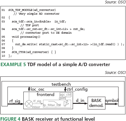
Predefi ned converter ports (‘sca_tdf::sc_out’ or ‘sca_ tdf::sc_in’) can establish a connection to a SystemC DE channel (e.g., ‘sc_signal<T>’), reading or writing values during the fi rst delta cycle of the current SystemC time step. Example 5 illustrates the use of such a converter port in a TDF module modeling a simple A/D converter with an output port to which a SystemC DE channel can be bound.

Electrical linear networks (ELN) are specifi ed by instantiating predefi ned network primitives, such as resistors or capacitors. As with LSF, the primitives can be instantiated in a regular ‘SC_MODULE’. To access the voltages or currents in the network, converters must be used. The SystemC AMS extensions provide converters that translate these voltages and currents to double-precision fl oating-point values in TDF and discrete-event models – and vice versa. Example 6 gives the ELN model of a low-pass fi lter implemented with one resistor primitive and one capacitor primitive. Since the intention is to use the model in a TDF context, additional converter primitives are used to convert TDF data sample values to voltages – and vice-versa.
As well as modeling LSF, TDF, and ELNs, the SystemC AMS extensions provide a means of tracing signals.
Modeling methodology example
To demonstrate the capabilities of the AMS extensions, a simplifi ed example is presented. The use of the AMS extensions is explained for the use cases shown in Figure 2:
- executable specifi cation at the functional level;
- architecture exploration at the functional, architecture, and implementation levels;
- integration validation; and
- virtual prototyping.

An executable specifi cation is made to verify the correct understanding of the system specifi cation by simulation. For this use case, data flow and signal flow are appropriate modeling styles. Note, that the executable specifi cation introduces structures and algorithms that are hard to change or modify later. Therefore, structures and algorithms that match the architecture must be carefully chosen. The specifi cation of the simple example is shown in Figure 4. It is a basic binary amplitude shift keying (BASK) receiver consisting of a mixer, a low pass fi lter, and a BASK demodulator. To verify the receiver specifi cation, it is modeled using TDF. To achieve good simulation performance we use TDF for the whole receiver model. We obtain data samples by oversampling the assumed continuous-time signals and represent them by double-precision values in the front end. We also assume that the BASK demodulator generates one symbol for every 20,000 input samples. Example 7 gives the TDF model of the BASK demodulator, assuming a DSPbased implementation.

Using the front-end module in Example 4, the TDF module of the BASK demodulator given in Example 7 and another module for the testbench, the structure of a model that can be used to evaluate the functional specifi cation in Figure 3, is given in Example 8. The architecture exploration stage evaluates and determines the key properties and comprises two phases. In the fi rst, the executable specifi cation is refi ned by adding non-ideal properties of an implementation to better understand the impact on overall system behavior. In the second, the architecture’s structure and interfaces are adapted to match the fi nal implementation to get a more accurate model. Note, that this also implies the use of different models of computation. For example, HW/SW architectures can be analyzed more accurately using cycle accurate or TLM modeling. In this example, the impact of mixer noise and distortion is evaluated in the fi rst phase. The ‘processing()’ method of the mixer in the executable specifi cation is refi ned by adding a simple behavioral model of noise (‘function my_noise()’) and by C++-code that models third-order non-linear distortion as illustrated in Example 9.

Other parameters such as bit widths, delays, time steps and rates can also be easily analyzed by refi nement of the executable specifi cation. For the evaluation of different sample rates, delays and time steps, the properties specified in the attributes section of TDF modules can be modifi ed. The impact of bit widths and quantization errors can be analyzed by replacing the fl oating-point data types in the ‘processing()’ methods with ‘sc_int<bw>’ fi nite-length integer types. In Example 10, different bit widths are evaluated by replacing the double-precision data type with a 16bit integer representation.
In the second phase of architectural exploration, the intended architecture is modeled more accurately (e.g., the low pass fi lter could be specifi ed by an electrical network). Given knowledge of the required sample rates and bit widths, an A/D converter between the low pass fi lter and the BASK demodulator is added. This determines the A/D partitioning as shown in Figure 5 and can be seen as a starting point for HW/SW co-design using SystemC. Instead of a full TDF model, a model that uses an A/D converter to translate the TDF signal ‘d_in’ to a cycle accurate or TLM signal ‘d_in_de’ can be developed. The interface to and modeling of the demodulator HW/SW system using pure SystemC is not covered here.
To prepare for the design of subsystems and integration validation, the interfaces of all subsystems must be modeled accurately. The interfaces and data types used in the models should match the implementation. For analog circuits, this relates to electrical nodes. For digital circuits, this relates to pin accurate buses. For HW/SW systems TLM interfaces might be appropriate. After the defi nition and design of the analog, digital HW and SW components, these components are integrated and their correctness is verifi ed within the overall system. The layered architecture of the SystemC AMS extensions encourages its use as a simulation backplane in which other simulators can be integrated via their C-language interfaces. In the BASK receiver example, the low pass fi lter and the mixer could be replaced by circuit-level models to validate the connectivity and integrity of the subsystems.
The AMS extensions are not intended to replace circuit simulators. The use of more accurate circuit simulators to verify circuit implementations can be applied, once an integration of a circuit simulator is available.
Virtual prototyping provides software developers with a high-level untimed or timed model that represents the hardware architecture.
Especially for E-AMS systems, where software is interacting with AMS hardware, interoperability with SystemC TLM extensions is important. In the BASK receiver example, the refi ned TDF model combines high simulation speed with appropriate accuracy to act as a virtual prototype for further development of the HW/SW subsystem. Then, the AMS subsystem becomes part of the virtual prototype. For systems that are more complex and realistic than the simple BASK example, SystemC AMS extensions support a similar refi nement methodology to SystemC that can be applied to the overall system by introducing hierarchical converter channels or adapters.
Summary
The SystemC AMS extensions enhance the available SystemC standard with support for linear electrical networks, linear signal flow, and timed data flow models to effi ciently model and simulate AMS architectures. New language constructs support the creation of AMS models at higher levels of abstraction, introducing functional and architecture-level modeling. This enables a design refi nement methodology for executable specifi cation, architecture exploration, integration validation, and virtual prototyping of E-AMS systems in a seamless, C-based environment. The extensibility supports application specifi c requirements (e.g., to model nonlinear or radio frequency behavior). Extending the unique capabilities of SystemC with new AMS features offers a powerful modeling and simulation framework, enabling design and verification for a wide range of applications and systems.
Authors
This article was written by Christoph Grimm, Vienna University of Technology, Martin Barnasconi, NXP Semiconductors, Alain Vachoux, Ecole Polytechnique Fédérale de Lausanne, & Karsten Einwich, Fraunhofer IIS/EAS Dresden.


