Mixed-signal verification of advanced SoCs using VCS AMS
How ST Microelectronics uses Synopsys’ VCS AMS, combining VCS functional verification and CustomSim, to verify one of its mixed-signal designs
The complexity of mixed-signal system-on-chip (SoC) designs is rapidly increasing due to growing analog content, advanced analog and digital interfaces and tougher requirements for safety and reliability. Synopsys introduced VCS AMS in early 2014, incorporating Synopsys’ VCS functional verification and the CustomSim FastSPICE simulator, to deliver the performance and capacity necessary for faster mixed-signal SoC regression testing. VCS AMS supports a SystemVerilog-based verification methodology, AMS Testbench, and a low-power verification technology based on UPF.
This article introduces VCS AMS and includes a case study on how STMicroelectronics uses VCS AMS to verify large IP and macro blocks. Helene Thibieroz of Synopsys discusses key features of VCS AMS. Pierluigi Daglio of STMicroelectronics highlights the use of VCS AMS to accelerate mixed-signal verification using techniques such as assertions and the save-and-restore capability.
Key features of VCS AMS
Helene Thibieroz, marketing manager in the analog mixed-signal group at Synopsys
VCS AMS provides the performance and flexibility needed for a modern mixed-signal verification system. Fast simulation engines and support for multicore simulation ensure transistor-level accuracy and higher throughput. It supports analog-on-top, digital-on-top and mixed-signal on-top design styles, and multiple languages, including SystemVerilog, Verilog VHDL, Verilog-AMS, SPICE, and SystemVerilog. Other critical capabilities include:
- Automated insertion of interface elements to avoid convergence or accuracy issues
- Diagnostic reports that enable early detection of design errors caused by complex inter-block connectivity or analog-to-digital interfaces
- Save and restore features to ease mixed-signal verification for regression tests
- AMS Testbench, which extends digital verification techniques to mixed-signal designs
- VCS Native Low Power (NLP) technology, enabling designers to carry their UPF power intent into the analog domain
Automated insertion of interface elements
More than half of failures in mixed-signal SoC design happen at the analog-to-digital (A/D) interface. VCS AMS automatically inserts those A/D interface elements, and optimizes them for simulation speed and accuracy.
Diagnostic reports
VCS AMS generates more than 10 connectivity reports, covering issues such as interface element type and positioning, port mapping and direction, connectivity between blocks, and supply voltages. This means that designers can get a critical report to enable debug of design connectivity errors early in the simulation process.
Save and restore
VCS AMS’ unique save and restore capability enables faster regression testing throughput by resuming simulation from a previously saved state.
AMS Testbench
Synopsys’ AMS Testbench extends digital verification strategies based on UVM to mixed-signal design. It includes predefined automated simulation generators, assertion-based checking logic, observation points defined by functional coverage, and verification planning.
Features include:
- checking connectivity between electrical and real conversion, for example, to check for asynchronous analog events within a digital testbench
- assertions and checkers for analog
- specific sources to mimic some analog characteristics
Low power verification
VCS AMS uses VCS NLP technology to enable it to pass power intent from the analog to the digital domain.
NLP enables VCS to read the UPF format. By enhancing NLP for analog, VCS AMS can control and monitor the power states for SPICE, extending UPF methodology to mixed-signal designs.
In the example pictured below, this specific design includes two power domains. The design power intent is being modeled in UPF and the required elements (such as level shifters and isolation cells) are being inserted to accurately represent the different power intents.
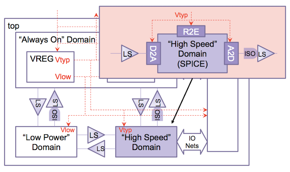
Figure 1 VCS AMS handles the conversion of UPF signals between digital and analog domains automatically (Source: Synopsys)
Let’s assume the high-speed domain block is now replaced by a SPICE model (in pink) to give greater accuracy. By extending NLP technology to analog, VCS AMS will automatically convert the digital input signal to the right analog level, ensuring the correctness of UPF power intent.
The translation of power intent from digital to analog includes several components:
- an automatic power supply adjustment, using real-to-electrical (R2E) interface elements, as shown in the diagram
- automatic positioning of interface elements to ensure that voltage levels are correctly evaluated
VCS AMS also includes static and dynamic circuit checks to identify electric rule violations and power-management design errors.
Using Synopsys CustomSim Circuit Check technology, mixed-signal designers can also identify violations such as missing level shifters, leakage paths and power-up checks at the SoC level.
Following is a case study case study on how STMicroelectronics uses VCS AMS in their mixed-signal verification flows.
How STMicroelectronics uses VCS AMS to verify large IP and macro blocks
Pierluigi Daglio, AMS design verification flows manager, STMicroelectronics
STMicroelectronics uses its simulation and verification environment to verify large IPs, macro-cells, and large AMS systems. The simulation and verification of AMS systems is done using a system-level analog/digital co-simulation with digital testbenches, because we find this approach easier to manage. We need fast and reliable simulation, and want to make the greatest possible use of hardware description languages for digital and analog blocks.
Our AMS verification flow is shown in Figure 2.
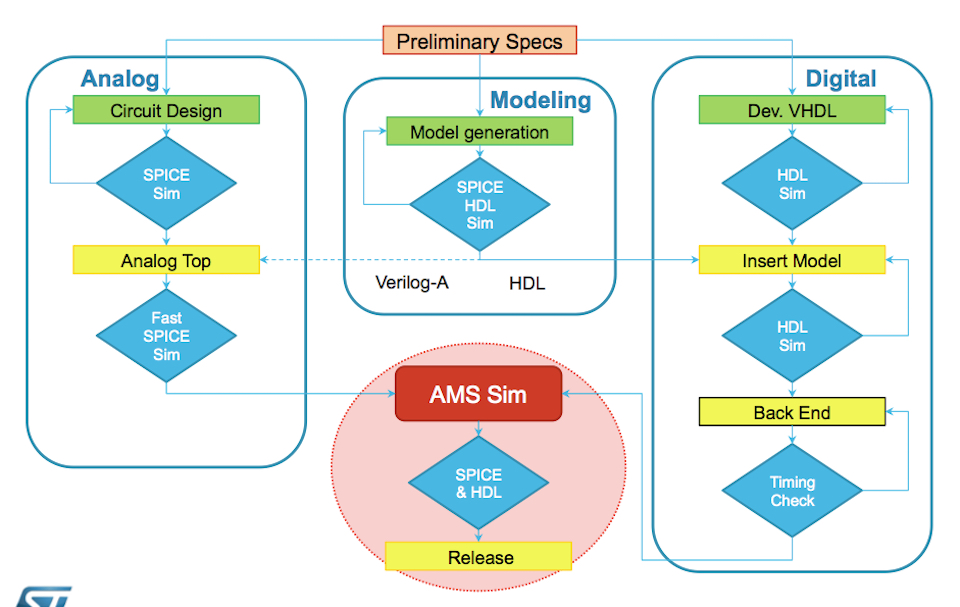
Figure 2 STMicroelectronics’ approach to verification checks analog and digital blocks separately before their integration (Source: STMicroelectronics)
Analog blocks are verified by running SPICE simulations of the circuit design. Digital blocks are developed in VHDL or Verilog. Once both analog and digital blocks reach the right level of maturity they are integrated at the top level.
We also develop VHDL and Verilog models for the digital parts of the design and Verilog-A and Verilog-AMS for the analog parts. These are checked with respect to the transistor-level description of the analog blocks and the specifications of the digital blocks.
We integrate the analog blocks at transistor level or as behavioral descriptions with digital blocks in VHDL or Verilog to form a mixed-signal schematic that is usually ‘analog-on-top’. This enables the verification of complex AMS designs, mixing elements such as a Verilog or VHDL digital netlists with a pre- or post-layout analog netlist, at the top level.
In the digital domain we can take into account the minimum and the maximum delays of the analog blocks. In the analog domain we can take into account the digital model corners (typical, minimum, maximum, fast-fast, slow-slow etc), as well as the user modes, such as for a memory block, its boot, read, erase, and program modes.
In use
Our test case for VCS AMS is an analog-on-top design. It has an embedded memory, built with digital circuitry, defined in VHDL and Verilog, and an analog circuit that includes sense amplifiers, and other related analog blocks.
The verification effort is driven by a digital testbench, because it is easier to manage.
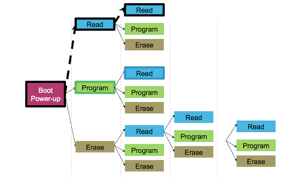
Figure 3 STMicroelectronics’ verification strategy for its analog-on-top design (Source: Synopsys)
The 136Kbyte memory block has two supplies, an analog supply from 1.6 to 3.6V, and a digital supply from 1.08 to 1.32V. It also has embedded program and array code.
With VCS AMS, we have taken advantage of the automatic checks with assertions. We declared a digital input, and analog output and the trigger signal. We specify the assertion to check that the content of the memory during the boot operation is equal to the content of the ROM that we use as a scoreboard.
With this mechanism, we can automatically have a flag set if there is a mismatch between the contents of the memory and the scoreboard.
We also took advantage of VCS AMS’s save and restore capability, which enables designers to run a simulation, save the results, change something in the netlist or in the set-up, and then run another simulation with another scope.
When you restore a saved simulation, the netlist and the setup cannot be changed, but you can change the operation. We use this to run many functional simulations of a design after power-up.
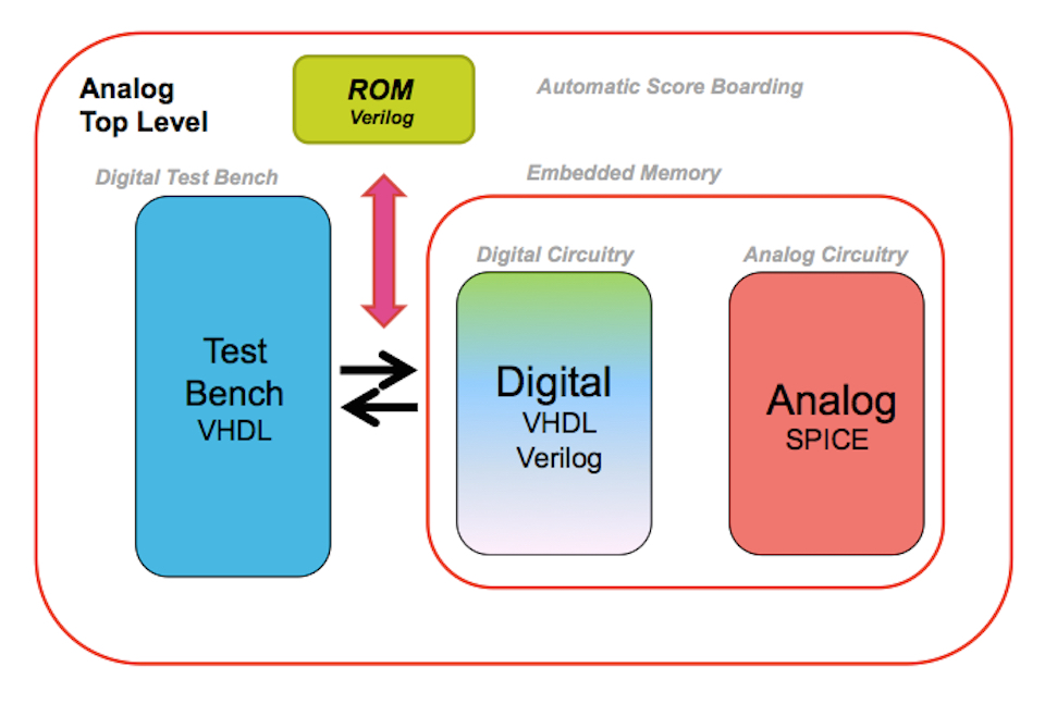
Figure 4 The Save and Restore function of VCS AMS can be used to avoid unnecessary repetition during verification (Source: STMicroelectronics)
You can define simulation multiple runs in the model testbench, which can then be executed by changing the value of a test selector variable.
In practice, we run the power-up of the memory and a read operation, save the status and then can restart from that point, running another read, program or erase operation.
In practice, a power-up simulation takes 90 minutes and a read operation a further 10 minutes. If we save the state at this point, we save 100 minutes every time we run another simulation from this point. We can save even more time with more complex operations such as program and erase.
Conclusion
Mixed-signal design engineers face increasing challenges in the verification of complex mixed-signal SOCs. To overcome these challenges, a mixed-signal verification solution that delivers industry-best performance and capacity, flexibility and advanced capabilities such as self-checking testbench and coverage-driven verification extended to analog is critical to accelerating mixed-signal SoC regression testing.
Further information
Find out more about Synopsys’ VCS AMS here
Author
Helene Thibieroz is marketing manager for mixed-signal verification at Synopsys.
Pierluigi Daglio is AMS design-verification flows manager, STMicroelectronics.
