Introducing new verification methods into a design flow: an industrial user’s view
Verification has become one of the main bottlenecks in hardware and system design. Several verification languages, methods and tools addressing different issues in the process have been developed by EDA vendors in recent years. This paper takes the industrial user’s point of view to explore the difficulties posed when introducing new verification methods into ‘naturally grown’ and well established design flows – taking into account application domain-specific requirements, constraints present in the existing design environment and economics. The approach extends the capabilities of an existing verification strategy with powerful new features while keeping in mind integration, reuse and applicability. Based on an industrial design example, the effectiveness and potential of the developed approach is shown.
Today, it is estimated that verification accounts for about 70% of the overall hardware and system design effort. Therefore, increasing verification efficiency can contribute significantly to reducing timeto- market. Against that background, a broad range of languages, methods and tools addressing several aspects of verification using different techniques has been developed by EDA vendors. It includes hardware verification languages such as SystemC1 2, SystemVerilog3 and e4 that address verification challenges more effectively than description languages such as VHDL and Verilog.
Strategies that use object-oriented mechanisms as well as assertionbased techniques built on top of simulation-based and formal verification enable the implementation of a more compact and reusable verification environment. However, introducing advanced verification methods into existing and well established industrial development processes presents several challenges. Those that require particularly careful attention from an industrial user’s point of view include:
- The specific requirements of individual target applications;
- The reusability of available verification components;
- Cost factors such as tool licenses and appropriate designer training.
This paper discusses how to address the challenges outlined above. With regard to the specific requirements of automotive electronics design, it identifies verification tasks that have high priority. For the example of the verification strategy built up at Bosch, the paper works through company-specific requirements and environmental constraints that required greatest consideration. Finally, the integration of appropriate new elements into our industrial design flow, with particular focus on their practical application, is described.
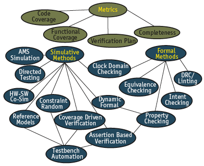
Figure 1. Verification landscape
Verification challenges
Recently, many tools and methods have been developed that address several aspects of verification using different techniques. In the area of digital hardware verification, metrics for the assessment of the status of verification as well as simulation-based and formal verification approaches have received most attention. Figure 1 is an overview of various approaches and their derived methods. Different design and verification languages and EDA solutions from different vendors occupy this verification landscape to differing degrees and in different parts.
Introducing new verification languages and methods into a well established design and verification flow requires more than pure technical discussion. Their acceptance by developers and the risks that arise from changing already efficient design processes must be considered – a smooth transition and an ability to reuse legacy verification code are essential.
Existing test cases contain much information on former design issues. Since most automotive designs are classified as safety critical, even a marginal probability of missing a bug because of the introduction of a new verification method is unacceptable. On the other hand, the reuse of legacy code should not result in one project requiring multiple testbench approaches. Legacy testcases should ideally be part of the new approach, and it should be possible to reuse and enhance these instead of requiring the writing of new ones.
A second important challenge lies in convincing designers to adopt new methods and languages. Designers are experienced and work efficiently with their established strategies. Losing this efficiency is a serious risk. Also, there is often no strict separation between design and verification engineers, so many developers can be affected when the verification method changes. Furthermore, new methods require training activities and this can represent a considerable overhead. Meanwhile, most projects must meet tight deadlines that will not allow for the trial and possible rejection of a new method.
To overcome those difficulties, it is important to carefully assess all requirements and to evaluate new approaches outside higher priority projects. One possibility is to introduce new methods as add-ons to an existing approach so that a new method or tool may improve the quality but never make it worse. In this light, the evolution of verification methodologies might be preferable to the introduction of completely new solutions.
Considering verification’s technical aspects, automotive designs pose some interesting challenges. The variety of digital designs ranges from a few thousand gates to multimillion-gate systemson- chip. Typical automotive ICs implement analog, digital and power on the same chip. The main focus for such mixed-signal designs is the overall verification of analog and digital behavior rather than a completely separate digital verification. However, the methodology’s suitability for purely digital ICs (e.g., for car multimedia) must also be covered.
In practice, the functional characteristics of the design determine what is the most appropriate verification method. If the calculation of the expected behavior is ‘expensive’, directed tests may be the best solution. If there is an executable reference model available or if the expected test responses are easy to calculate, a random simulation may be preferable. Instead of defining hundreds of directed testcases, a better approach can be to randomize the input parameters with a set of constraints allowing only legal behavior to be generated. In addition, special directed testcases can be implemented by appropriately constraining the randomization. The design behavior is observed by a set of checkers. Functional coverage points are necessary to achieve visibility into what functionality has been checked. Observing functional coverage and manually adapting constraints to meet all coverage goals leads to coverage-driven verification (CDV) techniques. Automated approaches built on top of different verification languages1 2 3 4 5 result in testbench automation (TBA) strategies.
A directed testbench approach may be most suitable for low complexity digital designs, particularly in cases where reference data is not available for the randomization of all parameters, or the given schedule does not allow for the implementation of a complex constraint random testbench. Furthermore, mixed-signal designs may require directed stimulation. Often a function is distributed over both analog and digital parts (e.g., an analog feedback loop to the digital part). Verifying the digital part separately makes no sense in this case. In fact, the interaction between analog and digital parts is error-prone. Thus, the integration of analog behavioral models is necessary in order to verify the whole function.
One technique that deals with this requirement maps an analog function to a VHDL behavioral description and simulates the whole design in a directed fashion. In other cases, the customer delivers reference data originating from a system simulation (e.g., one in Matlab6). Integrating that reference data within a directed testcase is mandatory. Since each directed testcase may be assigned to a set of features within the verification plan, the verification progress is visible even without functional coverage points. Hence, the implementation effort is less than for a constraint random and CDV approach up to a certain design complexity. Anyway, for some parameters not affecting the expected behavior (e.g., protocol latencies), it makes sense to introduce randomization.
Formal verification techniques like property checking allow engineers to prove the validity of a design characteristic in a mathematically correct manner. In contrast to simulation-based techniques – which consider only specific paths of execution – formal techniques perform exhaustive exploration of the state space. On the other hand, formal techniques are usually very limited in circuit size and temporal depth. Therefore, formal and simulation-based techniques need to be combined carefully to optimize the overall verification result while keeping the verification effort to a minimum.
The solution is to apply different verification techniques where they best fit. Powerful metrics are needed to ensure sufficient visibility into the verification’s progress and the contribution of each technique. The question is how to find the best practical solution within available time, money and manpower budgets rather than that which is simply the best in theory. The demands placed on verification methods reach from mixed-signal simulation and simple directed testing to complex constraint random and formal verification as well as hardware/software integration tests. Nevertheless, a uniform verification method is desirable, to provide sufficient flexibility and satisfy all the needs of the automotive environment.
Verification strategies
To illustrate one response to the challenges defined above, this section shows how SystemC has been applied to enhance a companyinternal VHDL-based directed testbench strategy. This approach allowed for the introduction of constraint random verification techniques as well as the reuse of existing testbench modules and testcases, providing the kind of smooth transition cited earlier.
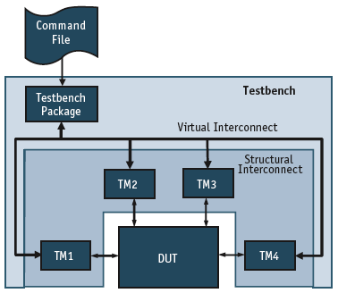
Figure 2. VHDL testbench approach
VHDL-based testbench approach
As Figure 2 shows, the main element in our testbench strategy is to associate one testbench module (TM) or bus functional model with each design-under-test (DUT) interface. All those TMs are controlled by a single command file. Each TM provides commands specific to its individual DUT interface. Furthermore, there is a command loop process requesting the next command from the command file using a global testbench package. Thus, a ‘virtual interconnect layer’ is established. Structural interconnect is required only between the TMs and the DUT.
The command file is an ASCII file containing command lines for each TM as well as control flow and synchronization statements. With its unified structure, this testbench approach enables the easy reuse of existing TMs.
Figure 3 is an example of the command file syntax. Each line starts with a TM identifier (e.g., CLK, CFG), the ALL identifier for addressing global commands (e.g., SYNC), or a control flow statement. Command lines addressing TMs are followed by modulespecific commands and optional parameters. Thus, line 1 addresses the clock generation module CLK. The command PERIOD is implemented within this clock generation module for setting the clock period and requires two parameters: value and time unit. Line 3 contains a synchronization command to the testbench package. The parameter list for this command specifies the modules to be synchronized (ALL for line 3; A2M and CFG for line 7). Since, in general, all TMs operate in parallel – and thus request and execute commands independently – it is important to synchronize them at dedicated points within the command file. When receiving a synchronization command, the specified TMs will stop requesting new commands until all of them have reached the synchronization point.
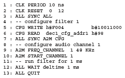
Figure 3. Command file example
Introducing a SystemC-based approach
The motivation for applying SystemC is to enhance the existing VHDL-based testbench approach. The original VHDL approach defined a sequence of commands which were executed by several TMs, describing a testcase within a simple text file. This worked well enough, but usage showed that more flexibility within the command file was desirable. Besides, VHDL itself lacks the advanced verification features found in hardware verification languages (HVLs) such as e, SystemVerilog HVL and SystemC, as well as the SystemC Verification Library (SCV).
Since the original concept had proved efficient, it was decided to extend the existing approach. In making this choice, it was concluded that a hardware description language like VHDL is not really suitable for the implementation of a testbench controller which has to parse and execute an external command file. So, SystemC was used instead because it provides the maximum flexibility, thanks to its C++ nature and the large variety of available libraries, especially the SCV. Using SystemC does require a mixed-language simulation – the DUT may still be implemented in VHDL, while the testbench moves towards SystemC – but commercial simulators are available to support this.
The implemented SystemC testbench controller covers the full functionality of the VHDL testbench package and additionally supports several extensions of the command file syntax. This makes the use of existing command files fully compliant with the new approach. The new SystemC controller allows us to apply variables, arithmetic expressions, nested loops, control statements and random expressions that are then defined within the command file. The intended impact of these features is that testcases run more efficiently and flexibly.
In general, the major part of testbench behavior should be implemented in VHDL or SystemC within the TMs. Thus, the strategy implements more complex module commands rather than very complicated command files. However, the SystemC approach does not only extend command syntax, it also provides static script checks, more meaningful error messages and debugging features.
Implementing the testbench controller in C++, by following an object-oriented structure, makes the concept easier to use. A SystemC TM is inherited from a TM base class. Hence, only module-specific features have to be implemented. For example, the VHDL-based approach requires implementation of a command loop process for each TM in order to fetch the next command. This is not the case with SystemC because the command thread is inherited from the base class – only the command functions have to be implemented. The implementation of features such as expression evaluation particularly shows the advantage using C++ with its many libraries (e.g., the Spirit Library7 is used to resolve arithmetic expressions within the command file).
Another important and practical requirement is that existing VHDL-based TMs can be used unchanged. SystemC co-simulation wrappers need to be implemented and they are generated by using the fully automated transformation approach described in Oetjens Gerlach & Rosenstiel8. All VHDL TMs are wrapped in SystemC and a new SystemC testbench top-level is built automatically. This allows the user to take advantage of the new command file syntax without re-implementing any TM, and the introduction of randomization within the command file means existing testcases can be enhanced with minimal effort.
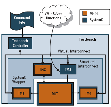
Figure 4. SystemC testbench approach
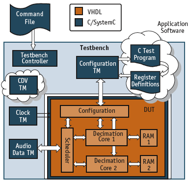
Figure 5. Decimation filter
Figure 4 shows a testbench environment that includes both VHDL and SystemC TMs. As a first step, legacy TMs are retained, as is shown for TM1, TM2 and TM4. Some TMs, like TM3, may be replaced by more powerful SystemC modules later. SystemC modules allow the easy integration of C/C++ functions. Moreover, the TMs provide the interface handling and correct timing for connecting a piece of software.
Design example
Some extended and new verification features were applied to our SystemC-based testbench approach for a specific industrial design, a configurable decimation filter from a Bosch car infotainment application. The filter is used to reduce the sampling frequency of audio data streams, and consists of two independent filter cores. The first can reduce the input sample frequency of one stereo channel by a factor of three, while the second can either work on two stereo channels with a decimation factor of two or one stereo channel with a decimation factor of four. The filter module possesses two interfaces with handshake protocols: one for audio data transmission and the other for accessing the configuration registers.
The original verification environment was implemented in VHDL, based on the legacy testbench concept described in “Verification strategies.” Besides a clock generation module, two testbench modules for accessing both the data transmission and the configuration interface were required. To fulfill the verification plan, a set of directed testcases (command files) was created.
Figure 5 shows the top-level architecture embedded within a SystemC-based testbench. The example demonstrates the smooth transition towards our SystemC-based testbench approach as well as the application of constraint random and coverage-driven verification techniques. This approach also proved flexible enough to offer efficient hardware-software co-verification.
Constraint random verification
The randomization mechanisms of the SystemC-based testbench were extensively used, and the associated regression tests uncovered some interesting corner cases. As a first step, the existing VHDL TMs were implemented in SystemC. No significant difficulties were encountered nor was any extra implementation time required. To check compliance with the legacy VHDL approach, all existing testcases were re-simulated. Since reference audio data was available for all the filter configurations, a random simulation could be implemented quickly with randomization techniques applied to both the TMs and the command file. The command file was split into a main file containing the general function and an include file holding randomized variable assignments. The main command file consisted of a loop which applied all randomized variables from the include file to reconfigure and run the filter for a dedicated time.
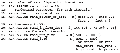
Figure 6. Constraint include file
Figure 6 illustrates an excerpt from the include file. Line 24 describes the load scenario at the audio data interface. The variable #rand_load was applied as a parameter to a command of module A2M later within the main command file. A directed test was enforced by assigning constant values instead of randomized items. Hence, the required tests in the verification plan could be implemented more efficiently as constraint include files. After the verification plan had been fulfilled all parameters were randomized for the running of overnight regressions and identification of corner cases.
Coverage-driven verification
Coverage metrics are required to monitor the verification’s progress, especially for random verification. Analyzing the code coverage is necessary but not in itself sufficient.
For this example, a set of functional coverage points was implemented using PSL5. Since PSL does not support cover groups and cross coverage, a Perl9 script was written to generate those cross coverage points. Implementing coverage points required considerable effort, but as a result of that work some verification ‘holes’ in our VHDL-directed testbench were identified. Considering the fully randomized testcase, all coverage points will eventually be covered. In order to meet the coverage goals faster and thus reduce simulation time, a more efficient approach defines multiple randomized testcases using stronger constraints.
Replacing the manual constraints extended our knowledge of TBA techniques with regard to the automatic adaptation of constraints due to the measured coverage results. Therefore, it was necessary to manually define dependencies between constraints and coverage items. Such a testbench hits all desired coverage points automatically. The disadvantage is the considerable effort needed to define the constraints, coverage items and their dependencies.
Nevertheless, a methodology based on our SystemC testbench and PSL was created. First, access to our coverage points was required. Therefore, coverage points were assigned to VHDL signals that could be observed from SystemC. Then, dependencies were identified between the coverage results and constraints within either the command file or a SystemC testbench module. To automate this step, improvements were made to the Perl script. Thus, a CDV testbench module was generated that either passed coverage information to the command file or could be extended for the adoption of constraints in SystemC.
HW/SW co-simulation
In the target application, the decimation filter is embedded within an SoC and controlled by a processor. To set up a system-level simulation, a vendor-specific processor model was given in C and Verilog. Hence, the compiled and assembled target application software, implemented in C, could be executed as binary code on the given processor model. However for this co-simulation, simulation performance decreased notably, although the actual behavior of the processor model was not relevant in this case.
The application C code consisted of a main function and several interrupt service routines. Control of the audio processing module (the decimation filter) was achieved by accessing memory-mapped registers. Thus, the processor performed read and write accesses via its hardware interface. To then overcome performance limitations, the processor model was omitted and the C code connected directly to a testbench module, as illustrated in Figure 5 (p.21).
Due to its C++ nature, the SystemC-based testbench approach offered a smart solution. The intention was to map the TMs’ read and write functions to register accesses within the application C code. Therefore, the existing register definitions were re-implemented, using an objectoriented technique. This allowed overloading of the assignment and implicit cast operators for those registers. Hence, reading a register and thus applying the implicit cast resulted in a read command being executed by the TM. Similarly, assigning a value to a register resulted in a write command being executed by the testbench module.
Finally, a mechanism was required to initiate the execution of the main and interrupt functions from the application C-code. Therefore, module commands to initiate those C-functions were implemented.
Hence, control and synchronization over the execution of those functions was available within our command file. This was essential to control the audio TM, which is required to transmit and receive audio data with respect to the current configuration. To execute the interrupt functions, the interrupt mechanism in our testbench concept was used.
Conclusions
Taking a company-internal VHDL-based testbench approach as an example, a smooth transition path towards advanced verification techniques based on SystemC can be demonstrated. The approach allows the reuse of existing verification components and testcases. Therefore, there is some guarantee that ongoing projects will benefit from new techniques without risking the loss of design efficiency or quality. This maximizes acceptance of these new techniques among developers, which is essential for their successful introduction.
Acknowledgements
This work was partially funded by the German BMBF (Bundesministerium für Bildung und Forschung) under grant 01M3078. This paper is abridged from the version originally presented at the 2007 Design Automation and Test in Europe conference in Nice.
References
- Open SystemC Initiative (OSCI), SystemC 2.1 Library, www.systemc.org
- Open SystemC Initiative (OSCI), SystemC Verification Library 1.0, www.systemc.org
- IEEE Std 1800-2005, IEEE Standard for SystemVerilog – Unified Hardware Design, Specification, and Verification Language
- IEEE Std 1647-2006, IEEE Standard for the Functional Verification Language ‘e’
- IEEE Std 1850-2005, IEEE Standard for Property Specification Language (PSL)
- The MathWorks homepage, www.mathworks.com
- Spirit Library, spirit.sourceforge.net (NB: no ‘www’)
- J.H. Oetjens, J. Gerlach, W. Rosenstiel, “An XML Based Approach for Flexible Representation and Transformation of System Descriptions”, Forum on Specification & Design Languages (FDL) 2004, Lille, France.
- Wall, Larry, et.al., Programming Perl (Second Edition), O’Reilly & Associates, Sebastopol, CA., 1996.
- IEEE Std 1076.3-1997, IEEE standard for VHDL synthesis packages


