Why emulation performance doesn’t matter (on its own)
Emulation performance is a key metric in verification. But it is far from being the only consideration. How long it takes to get a design onto a verification platform and aspects such as debug are as important. These factors will control how verification platforms are deployed during a project’s life cycle.
A key reason for introducing hardware acceleration to a verification flow is performance. As SoC designs increase in size, the use of emulation and other hardware accelerators to analyze full-chip functionality has become essential to ensure that tapeout schedules can be met. But, although often quoted as the primary factor, the raw cycle-time performance is only one metric. It needs to be analyzed in context.
The cycle speed is analogous to the horsepower rating of a car engine. Although horsepower is a key component of car performance in day-to-day use the engine’s peak output can rarely be put to use. You can use the speed on a long stretch of clear freeway. But many trips are short and do not warrant a detour to the freeway even if it is a faster stretch of road. For the shortest trips, just finding the keys, pulling the car out of the garage and onto the road become significant components of the overall time taken. Even on a long trip, you may want to pull off the freeway and onto the slower roads to explore the local scenery.
Similarly, the overall speedup that emulation and related techniques bring to verification relies on a number of factors that depend on where the project is within its life cycle, and how often the engineer needs to stop the simulation to take a closer look at something. The result is that every verification tool at our disposal has a sweet spot that lends itself to certain uses within the overall flow.
Four elements
There are four components to determining the overall performance of a simulation or simulation-acceleration tool in a particular situation: verification setup; resource allocation; runtime performance; and debug access.
For example, RTL simulation on a workstation is easy and quick to set up. It provides excellent debug access but its execution is slow. Conversely, a FPGA-based virtual prototype offers considerably less debug visibility, takes far longer to create – often a matter of weeks – but can offer five orders of magnitude higher cycle rates. Further, once the FPGA prototype has been created, any RTL changes after bugs are found need to be incorporated in a new model, which takes far more time than with a software-only simulation.
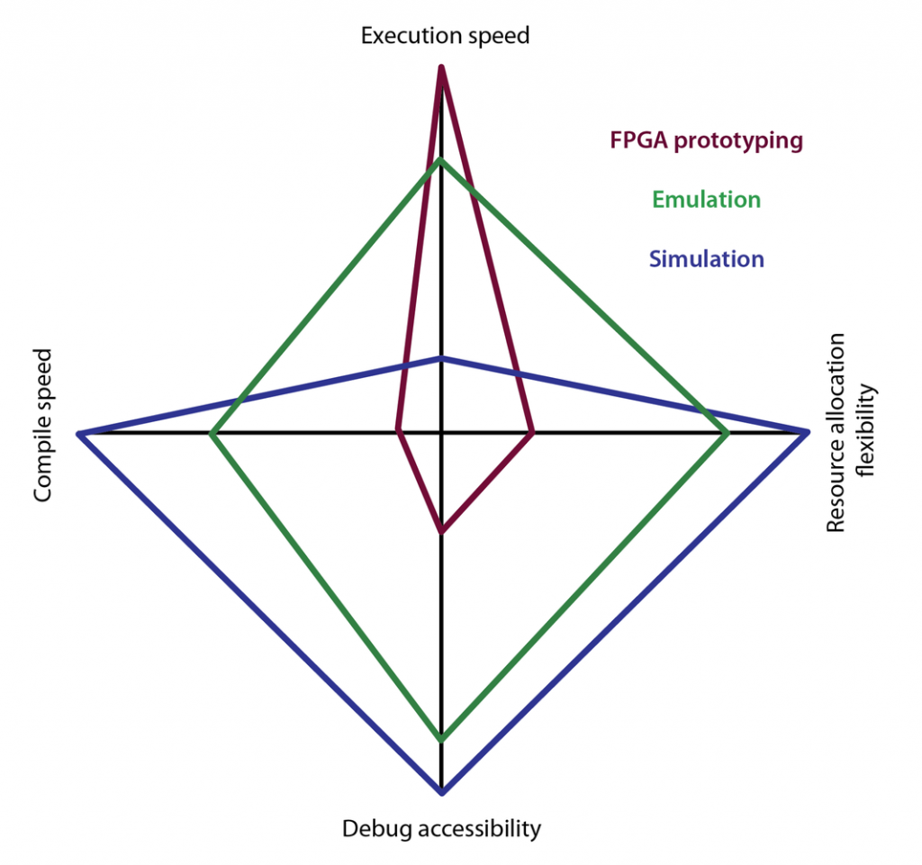
Image Radar diagram of the three key verification platform technologies
Software-only simulation is slow, perhaps hundreds of clock cycles per second for even moderately sized designs. But there are ways to improve aggregate performance through parallelization. The availability of server farms makes it possible to roll out hundreds or even thousands of simulation, each probing a different aspect of the design, to provide much higher coverage than a single workstation. Additional capacity can be added at critical times by offloading some of the simulation work to cloud services such as Amazon S3.
However, the parallelization of simulations only suits situations where the testbench can be readily partitioned and where the stimuli involved are logically independent. Some bugs are hidden deep in a design and can only be uncovered after significant simulation time on a single testbench. Total design size is also a factor.
Emulation performance
Much higher single-user performance is available through emulation. However, emulation still provides the ability to support parallel jobs so that capacity not needed for a given task can be allocated to others. The FPGA prototype, however, is optimized for a single hardware image and a single user. This, in itself, may become a bottleneck if multiple engineers need access to accelerated simulation.
Although compile time for an emulator is higher than for classic, manual FPGA based prototyping, the times are predictable. The Palladium emulation environment compiles at up to 70 million gates per hour. This allows full SoC designs to be compiled in less than a day and deliver a verification environment from that point able to operate at approximately 1MHz.
FPGA prototyping can support cycle times of more than 10MHz, often running in the 100MHz range. But the amount of work needed to get to that speed is far less predictable. The DUT needs to be rearchitected to suit the logic environment of the FPGA, demanding changes to the way that memories, for example, are instantiated and accessed. It then needs to be split manually across multiple FPGAs, which can generally only hold a proportion of the total DUT before the automated place-and-route stage.
If the design cannot complete the routing stage – which is a common problem due to the comparatively scarce routing resource available in programming logic – the design has to be repartitioned and reoptimized before starting again.
FPGA porting time
The process of determining whether the place-and-route will succeed is itself lengthy. Compilation for FPGAs may proceed at 5 million gates per hour for a 100 million-gate design. The result is that it takes a full-calendar day before the team can gauge whether the compile has succeeded. In practice, it can take four weeks for even an efficient development process to result in a working FPGA prototype.
Although the execution speed for the DUT is higher on the FPGA prototype by up to three orders of magnitude, the time it takes to complete the port represents a lost opportunity for verification if it is not used in combination with emulation. An emulator can run hundreds of hours of tests at 1MHz before the prototype is up and running, with greater access to debug and the ability to render changes to the RTL reasonably quickly.
There are tradeoffs in the FPGA prototyping flow that provide a compromise in performance and turnaround time. For example, a fully automated flow on the Protium platform – which is using the same front-end flow that Palladium uses – will typically provide the ability to run designs at 3MHz to 10MHz, with a compile speed of xxx million gates per day. With some manual guidance and the addition of dedicated memory cards, performance can be increased to the 10MHz to 30MHz range. With more manual optimization, essentially overriding the automation, even higher speeds can be achieved as described above, including the set-up caveats.
Debug decisions
However, debug remains a bigger area of distinction between emulation and FPGA prototyping than between software-only simulation and emulation. Simulation provides the engineer with the ability to probe any signal in the design more or less at will. The worst case is that they may have not tagged the right signals and have to adjust the test environment to retag but that is a straightforward and fast process.
Emulation can provide visibility in all parts of the design, with the key decision being which signals to buffer ready to pass out to waveform viewer and other debug and analysis tools. The trace buffer on Palladium, for example, can buffer up to 2 million cycles of target signals, which provides a great deal of flexibility and history data needed to track down complex bugs.
The ability to stream data out at high speed provides highly useful material for analysis that enables improvements in the power and energy efficiency of an SoC design. Once captured on a workstation, the toggle and other power-related data can be imported into an analysis tool to gauge the overall energy consumption of the recorded activity.
FPGA-based platforms have, in contrast, much more limited debug access. To gain the benefit of full-speed execution, the only signals that can be traced effectively are those designated as I/Os. Although an FPGA prototyping platform may add probing capability for arbitrary internal signals, the cost is in execution speed, which can drop by as much as a hundred-fold.
In-circuit verification
The relationship between the DUT and its environment can be exercised in different ways based on the verification platform. Simulation provides a large range of opportunities for intelligent test-bench generation strategies, as does emulation hardware through simulation-acceleration support.
FPGA and emulation provide the opportunity to operate the virtual SoC in-system as the clock rates are high enough to exercise the system using real-world I/O translated down to the DUT’s clock speed using specialized bridges and smart buffering.
As can be seen, the metric of simulation and emulation performance – that is, the execution of the design with test bench once set up – cannot be taken alone when evaluating the appropriate use of a particular verification platform. It is as much question of where the design lies in its lifecycle and how that fits the attributes of how quickly the platform can be brought online, how much debug access it provide and its ability to support multiple verification jobs.
Performance tradeoffs
As the design progresses towards completion fewer major changes will be made to the design. At the same time software for the proposed SoC starts to become available. At this point, the team can accept longer deployment times to reap the benefit of greater performance to test the software under conditions that reflect real-world use.
There is also scope for hybrid models in which emulation is deployed to bring the DUT to a certain state – after the booting of an operating system, for example – before then the verification process is carried out on a different platform, such as software-only simulation that provides a different level of interactivity and support for rapid design changes.
Hybrid usage models allow the performance characteristics of each platform to be used to full advantage. By taking into account the full spectrum of performance characteristics, verification teams can make better informed choices about when and how to deploy acceleration and ensure the most time possible is spent productivity: ensuring the SoC is ready for tapeout on schedule.
Author
Frank Schirrmeister is senior group director, product management in the system and verification group at Cadence Design Systems.
Company Info
Cadence Design Systems, Inc.
2655 Seely Avenue
San Jose CA 95134
(408) 943 1234
(408) 428 5001
www.cadence.com
