Design space exploration finds hotspots during early process development
A new technique has been developed to catch potential new lithography issues when little design data is available for incoming nodes.
Design rules define the allowed and forbidden design constructs for a given process technology. The information enables the development of comprehensive and compact test patterns. The patterns are crucial to the accurate and timely development of new semiconductor technologies. However, during new process node development, there may be few real designs to provide the necessary layout information for defining and testing design constraints.
A new pattern-based approach, known as design space exploration (DSE), is a way of generating and testing layout geometries during the early stages of process node development.
Lithographic pattern matching
In advanced technology nodes, pattern-matching has been widely adopted to reduce the amount of data sent to lithographic simulation and thereby improve simulation runtimes. Lithographic pattern matching augments standard design rule checking (DRC). It does so by applying fast 2D pattern matching to design layouts to find problematic 2D configurations that are difficult to manufacture.
However, during process development at 14nm and below, complex patterning issues cannot be easily anticipated or extrapolated from known physical process limitations. At the same time, traditional test sites are not sufficient to cover the rapidly increasing number of complex 2D patterning variations that can potentially exist in real designs at these nodes. This need is greatest during the early phases of building a new technology when there are few real designs.
How can designers find the geometries most likely to create lithographic failures (lithographic hotspots) in new processes in a timely and comprehensive manner? The ability to explore the design space to find patterns that identify hotspot candidates is crucial, as is the ability to implement this exploration in a seamless and a fast flow. Identifying these patterns early in the process development enables the faster development of design rules that can prevent problematic patterns from being used in real designs, providing significant value to design companies and foundries.
Design space exploration
DSE allows engineers to randomly generate realistic design-like layouts that pass all known design rule checks (DRCs). They then perform lithographic simulation on these layouts to discover potentially problematic patterns (hotspots) across process windows. Next, they introduce variations to the hotspot patterns and re-run lithographic simulation on all the variations. The results enable classification of the patterns in two groups:
- Forbidden patterns that should be included in the design rule checker
- Legal patterns that need better handling in the RET recipes and processes.
Figure 1 illustrates the overall DSE flow.
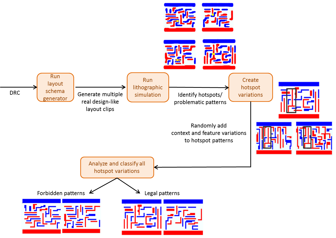
Figure 1: The design space exploration flow identifies hotspots early in process development (click to enlarge – all graphics: Mentor).
Layout schema generator
The secret to DSE success is a layout schema generator (LSG). It is a Monte Carlo-based process that generates clips of arbitrary layout patterns that comply with all known design rules for the targeted process. Each clip is created by randomly placing unit patterns in a grid, where the random placement is guided by user-defined rules and weights. Figure 2 shows an LSG process generating colored layouts for double- and triple-patterning applications, as well as standard cell-like layouts with predefined power rail templates.
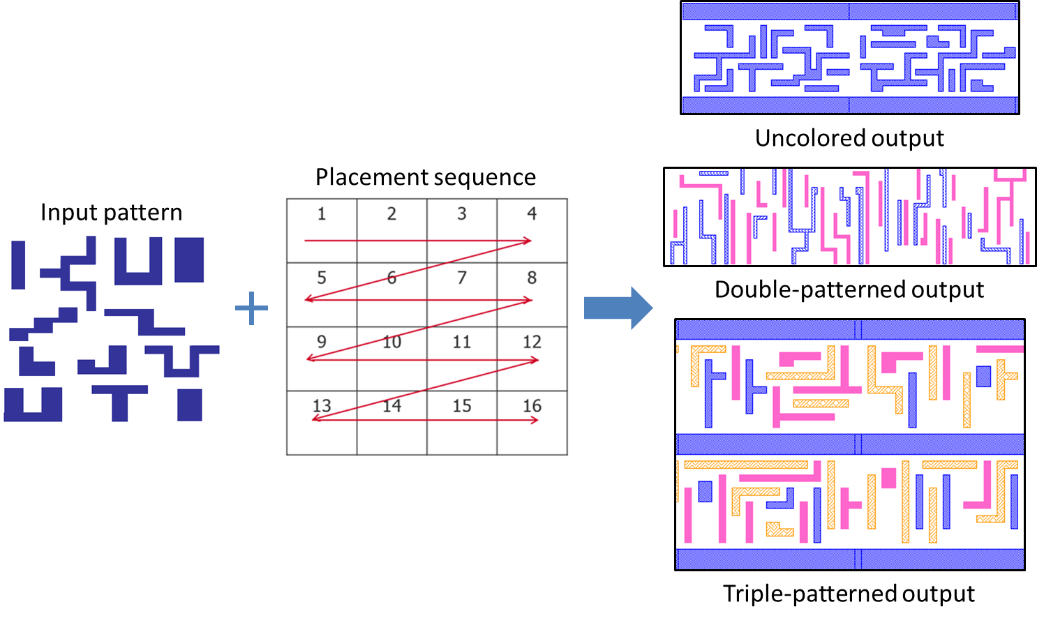
Figure 2: Layout schema generator functionality lets designers generate realistic layouts that are DRC-clean (click to enlarge).
The designer then uses lithography simulation on these layouts to identify potentially problematic patterns (lithographic hotspots). The hotspot patterns can then be further explored by randomly introducing feature and context variations using a hotspot variation flow (HSV) and re-running lithographic simulations.
Hotspot variation flow
The HSV lets designers generate different versions of an original hotspot by changing the context of the polygon/area in which the hotspot is located, with the intent of identifying how context affects the formation of a hotspot (Figure 3).
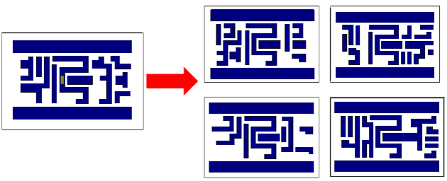
Figure 3: The context of the original pattern is changed to produce multiple variations of the pattern.
Figure 4 shows how the HSV flow allows the user to define both the extent region (the layer that defines the area of interest) with the size of the output clips, and the ignore region (the layer that defines the region representing the context of the hotspot to be randomized by the LSG process).
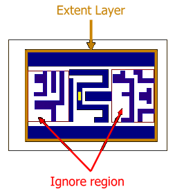
Figure 4: Both extent and ignore regions can be defined by the user in the HSV process.
Designers then perform lithography simulation on all of these variations, and classify the output variations into clean and hotspot patterns (Figure 5). There are two potential outcomes for any single hotspot pattern:
- Clean patterns are legal patterns that can become hotspots, depending on context. They require additional handling in resolution enhancement techniques (RET) recipes and processes to prevent their transition to actual hotspots.
- Hotspot patterns are problematic patterns that generate hotspots regardless of context. These configurations must be defined in the process node design rules as forbidden patterns, and a design rule check must be created to detect for their presence in a layout.
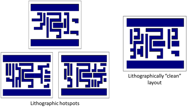
Figure 5: HSV validation identifies the occurrence of lithographic hotspots among all the pattern variations.
Experiments
We tested the design space exploration flow on a 14nm technology node. We used the Calibre LFD LSG functionality to randomly generate 2,000 layout clips, each 60um x 55um in size. Then, we ran lithographic simulation on all of these clips, and identified four clips that contained lithographic hotspots (Figure 6).
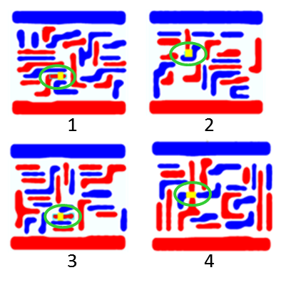
Figure 6. Four lithographic hotspots were identified after lithographic simulation.
We used the Calibre LFD HSV flow to generate 100 variations for the context of each of these hotspot patterns, while making sure the core pattern polygons that surrounded the hotspot location remained unchanged. The HSV flow then automatically analyzed and classified the generated variations into hotspots and clean patterns.
- 20% of the variations for the 1st hotspot are hotspots
- 80% of the variations for the 2nd hotspot are hotspots
- 99% of the variations for the 3rd hotspot are hotspots
- 100% of the variations for the 4th hotspot are hotspots
These results led us to the following conclusions:
- The 1st and 2nd patterns are legal patterns that depend on context. To avoid hotspot creation, they require additional handling in RET recipes and processes.
- The 3rd and 4th patterns are problematic patterns that will generate a hotspot regardless of context. They should be designated forbidden patterns, and these configurations should be added to the DRC to ensure they are not allowed in designs.
Conclusions
The design space exploration process for the early detection of problematic lithography patterns helps designers overcome the lack of real design data during process development and optimization. The DSE process generates random real design-like layouts that can be lithographically simulated to detect hotspot patterns. These hotspots are further explored by adding different contexts and variations around the core of the hotspot locations. After lithographic simulation of these variations, designers can identify which patterns should be added to the forbidden pattern list, and which patterns can be passed to optical proximity correction (OPC) process engineers to further optimize the OPC recipes.
A DSE flow can be adopted in all advanced nodes to provide an accurate and robust flow for the early identification and classification of lithographic hotspot patterns.
About the authors
Wael ElManhawy is a Lead Technical Marketing Engineer supporting Calibre LFD tools and technologies in the Design to Silicon division of Mentor, a Siemens Business. He has 20 years of experience in the EDA and semiconductor industries. Wael received his MSc in Device Modeling of Double Gate MOSFETs from Cairo University. He can be reached at waelUNDERSCOREmanhawyATmentorDOTcom
Joe Kwan is the Product Marketing Manager for Calibre LFD and Calibre DFM Services in the Design to Silicon division at Mentor, a Siemens Business. He previously worked at VLSI Technology, Compass Design Automation, and Virtual Silicon. Joe received a BA in Computer Science from the University of California, Berkeley, and an MS in Electrical Engineering from Stanford University. He can be reached at joeUNDERSCOREkwanATmentorDOTcom.
