Choosing between DDR4 and HBM in memory-intensive applications
Exploring the tradeoffs between implementing DDR4 and HBM for high-bandwidth memory subsystems.
It has always been a battle to balance the performance of processors and the memory systems that provide their raw data and digest their results. As advanced semiconductor process technologies further concentrate computing power on individual die, the issue is becoming acute, especially in applications such as high-end graphics, high-performance computing (HPC), and some areas of networking.
The heart of the problem is that processor performance is growing at a rate that eclipses that of memory performance. Every year the gap between the two is increasing.
Memory makers have been bridging this gap with successive generations of double data rate (DDR) memories, but their performance is limited by the signal integrity of the DDR parallel interface and the lack of an embedded clock as used in high-speed SerDes interfaces. This leaves system designers with multiple memory issues to solve: bandwidth, latency, power consumption, capacity and cost. The solutions for higher memory bandwidth are simple: either go faster and/or go wider. If you can improve latency and cut the energy consumed per bit transferred, that is a bonus.
The high bandwidth memory alternative
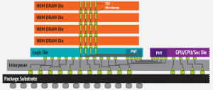
One approach to solving the memory problem is high bandwidth memory (HBM), which uses a stack of JEDEC-standard HBM SDRAM dice connected to a host SoC, typically via a 2.5D interposer as shown in Figure 1.
Figure 1 Cross-section of an HBM stack (Source: AMD)
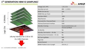
The approach used by HBM2 SDRAM, the second generation of HBM SDRAMs, enables the creation of a very wide point-to-point bus operating at modest data rates. HBM2 supports 1024 data pins per HBM2 stack operating at up to 2000Mbit/s per pin resulting in a total bandwidth of 256Gbyte/s. Future increases to data rates of 2400Mbits/s will see that increase to 307Gbyte/s. Since a 1024 bit wide interface will access too much data per read/write access for the system to efficiently use, the HBM2 interface is broken up into eight independent 128bit wide channels. HBM dice stacks (of 2, 4 or 8 dice) are interconnected using through-silicon vias (TSVs), which connect to a logic die at the bottom of the stack as shown in Figure 2. The logic die connects to the 2.5D interposer, which enables connections to other devices sharing the interposer, such as an FPGA or CPU, as well as providing suitable connections to the package.
Figure 2 The memory stack and logic die connect to a 2.5D interposer (Source: AMD/SKHynix)
HBM has enabled designers to concentrate large amounts of memory close to processors, with enough bandwidth between the two to redress the growing imbalance between processor and memory performance. This is proving attractive in HPC, parallel computing, data center accelerators, digital image and video processing, scientific computing, computer vision, and deep learning applications.
Key features of HBM2 SDRAMs
HBM2 builds on some of what has gone before in the definition of DDR. For example, each HBM2 channel is similar to a DDR interface, using similar commands and timing parameters. Because the available pin density of connecting a DRAM to an SoC is much higher with HBM2 versus DDR, this has enabled some architectural changes in the interface to HBM2. For example, ‘column commands’ for read/write and ‘row commands’ to precharge and activate memory cells are now separated (rather than being multiplexed as on DDR), reducing bus congestion.
HBM2 also has a ‘pseudo channel’ mode, which splits every 128bit channel into two semi-independent sub-channels of 64 bits each, sharing the channel’s row and column command buses while executing commands individually. The benefit of increasing the number of channels this way is increased overall effective bandwidth by avoiding restrictive timing parameters such as tFAW which allows more bank activates per unit time.
The DRAM input receivers may implement and use an optional internal VREF generator to allow more precise threshold control of input sensing levels. This helps to reduce the effect of process variability and improve receiver robustness.
HBM2 uses a single bank refresh command to refresh a single bank while accesses to other banks including writes and reads are unaffected. There is optional ECC support, enabling 16 error detection bits per 128 bits of data. The HBM2 standard also allows command/address parity checking, and data bus inversion to reduce simultaneous switching noise. It is also possible to remap interconnect lanes to help improve the assembly yield of silicon in package approaches, and to recover the functionality of a defective HBM2 stack.
Comparing DDR and HBM
How does the connectivity of DDR and HBM compare? With DDR4 and 5, the DRAM die are packaged and mounted on small PCBs which become dual inline memory modules (DIMMs), and then connected to a motherboard through an edge connector. For HBM2 memory, the hierarchy begins with DRAM die, which are then stacked and interconnected using TSVs, before being connected to a base logic die, which is turn is connected to a 2.5D interposer, which is finally packaged and mounted on the motherboard.
In terms of system capacity, DDR4/5 SDRAMs can use registered DIMMs (RDIMMs) or load-reduced DIMMs (LRDIMMs) to reduce critical fanout for speed for large capacity solutions. Some DDR4/5 DIMMS are also using packaged DRAMs which have stacked die inside them to increase package/DIMM capacity. Using state-of-the-art DRAM die stacking, two-rank RDIMMs can currently carry up to 128GByte of memory. With high-end servers having up to 96 DIMM slots, the theoretical memory capacity possible with DDR4 is up to 12TByte of SDRAM.
For HBM2, the numbers are a little different. Each packaged HBM2 DRAM may have up to eight stacked DRAM die, which with the highest capacity HBM die today each offering 8Gbit, makes for an 8GByte HBM2 stack. If the host SoC has four HBM2 interfaces, that means the system can have up to 32GByte of very high bandwidth local SDRAM.
Thermal requirements also play an important part of system design tradeoffs. A DDR based memory subsystem using DIMMs will reside in a reasonably large volume, with the SDRAM located some distance from the host SoC and often orthogonal to the motherboard. Fan cooling can dissipate the heat, and some high-performance systems are starting to use liquid cooling systems, although these are expensive. An HBM based system, on the other hand, will take up much less volume per Gbyte/s than a DDR based approach and is likely to be smaller. The SDRAMs in an HBM system are closer to the SoC, and mounted in the same plane as it and the host motherboard which should simplify cooling the design. The downside of the dense integration of memory die in HBM is that they can overheat, and so the devices contain a catastrophic temperature sensor output, which trips to stop permanent damage. The density of HBM systems also demands more elaborate heat sinks and air-flow management systems, and often liquid cooling.
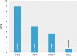
The shorter paths between memory and CPU on HBM2 systems mean that they can run without termination and consume much less energy per bit transmitted than terminated DDR systems. It can be useful to think about this being measured in picoJoules per bit transmitted, or milliwatts per Gigabit per second. The same kind of metrics can be applied to express the power efficiency of the DDR or HBM PHY on the hot SoC, a comparison of which is shown in Figure 3.
Figure 3 SoC DRAM PHY energy efficiency comparison (Source: Synopsys)
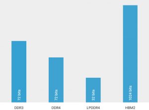
Building the PHY also means making tradeoffs. The PHY for an HBM2 implementation is larger than that for a DDR interface, because it demands many more off-die connections via a 23 x 220 array defined by the JEDEC HBM2 DRAM bump pattern. Such a large off-chip interface can also demand a lot of local decoupling capacitance, which if implemented on-chip may demand several square millimeters of die area.
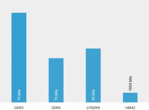
There are two ways of looking at the relative sizes of DDR and HBM PHY implementations. On the basis of area alone, an HBM implementation is likely to be larger than more traditional options (Figure 4). However, on a systemic comparison of relative PHY area per Gbit/s of bandwidth, HBM is much more area efficient (Figure 5).
Figure 4 SoC DRAM PHY relative area comparison (Source: Synopsys)
Figure 5 SoC DRAM PHY relative area per Gbit/sec of bandwidth (Source: Synopsys)
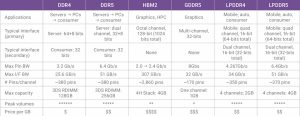
To sum up this comparison, DDR4 memory subsystem implementations are useful for creating large capacities with modest bandwidth. The approach has room for improvement. Capacity can be improved by using 3D stacked DRAMs, and RDIMMs or LRDIMMs. HBM2, on the other hand, offers large bandwidth with low capacity. Both the capacity and bandwidth can be improved by adding channels, but there is no option for moving to DIMM style approach, and the approach already uses 3D stacked die. A comparison of present (DDR4, HBM2, GDDR5 and LPDDR4) and future (DDR5, LPDDR5) DRAM features is presented in Figure 6.
Figure 6 Comparison of memory system features and benefits (Source: Synopsys)
A hybrid solution, which implements both HBM2 and DDR4 on the same SoC, can achieve the best of both worlds. Designers can achieve a large capacity on the DDR bus and a large bandwidth on the HBM2 bus. In system design terms, therefore, it may make sense to use the HBM2 memory as an L4 cache or closely-coupled memory, and the DDR4 memory as a higher performance alternative to Flash or an SSD.
Implementing HBM
Synopsys has introduced a DesignWare HBM2 PHY, delivered as a set of hard macrocells in GDSII that includes the I/Os required for HBM2 signaling. The design is optimized for high performance, low latency, low area, low power, and ease of integration. The macrocells can be assembled into a complete 512- or 1024-bit HBM2 PHY.
The IP comes with an RTL-based PHY Utility Block, which supports the GDSII-based PHY components and includes the PHY training circuitry, configuration registers and BIST control. The HBM2 PHY includes a DFI 4.0-compatible interface to the memory controller, supporting 1:1 and 1:2 clock ratios. The design is compatible with both metal-insulator-metal (MIM) and non-MIM power decoupling.
To simplify HBM2 SDRAM testing, the DesignWare HBM2 PHY IP provides an IEEE 1500 port with an access loopback mode for testing and training the link between the SoC and HBM2 SDRAM.
The IP also comes with verification IP which complies with the HBM JEDEC specification (including HBM2) and provides protocol, methodology, verification and productivity features including built-in protocol checks, coverage and verification plans, and Verdi protocol-aware debug and performance analysis, enabling users to achieve rapid verification of HBM-based designs.
Further information
The DesignWare HBM2 PHY and VC Verification IP are available now for 16nm, 14nm, 12nm and 7nm process technologies, with additional process technologies in development.
Author
Graham Allan joined Synopsys in June 2007. Prior to joining Synopsys, Allan was with MOSAID Technologies as director of marketing for semiconductor IP. With more than 25 years of experience in the memory industry, Allan has spoken at numerous industry conferences. A significant contributor to the SDRAM, DDR and DDR2 JEDEC memory standards, Allan holds 25 issued patents in the area of memory design.
