Bringing a coherent system-level design flow to AMS
For two decades, the benefits of ESL and abstractions have been supposedly confined to engineers working on digital designs and to system architects. Analog and mixed-signal (AMS) design has largely remained a ‘circuit level’ activity. This article shows that tools exist that now also allow AMS engineers to exploit abstraction, and that can make all types of design flow (analog only, but also where AMS/RF and digital elements are combined) more efficient and more comprehensive.
Software such as Simulink provides access to an extensive range of models, and the same tools can also provide a common communications platform between AMS and digital teams that helps both sides see how one part of a design affects another. Even at the level of the specification itself, cumbersome and sometimes ambiguous paper documentation can be replaced with digital files that define goals and intent throughout the life of a project.
There is a widespread belief that analog and mixed-signal (AMS) design cannot take advantage of abstractions and other ESL design techniques that have shortened design cycles and raised efficiency in the digital domain. This article will show that the reverse is true. Although the first generation of ESL tools tended to focus on linking hardware and software, there are ESL tools that enable AMS engineers to design at the system level and exploit the productivity advantages of ESL. These tools also improve the design and verification of the interface between the analog and digital worlds, where experience shows us that many bugs lurk.
Changing any design flow does involve some risk, sometimes a considerable amount. However, the techniques discussed here are at the lower end of that scale, and demonstrate that even a few minor tweaks can have a dramatic effect.
Source: The MathWorks
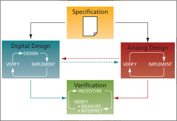
FIGURE 1 A typical AMS/digital design flow
The status quo
First, let’s identify some existing problems that we can fix in a straightforward way. Figure 1 shows a typical AMS design flow that we will use as a vehicle.
A project usually starts with a specification. An internal team—perhaps ‘a research group’ or ‘a systems and algorithms group’—creates models of the proposed system and starts running conceptual simulations. It then passes the resulting goals on to the digital and analog design groups for the implementation stage. The specification normally arrives as a paper (e.g., Acrobat, Word) document.
At this point, the two teams go off and design their parts of the system. In principle, there should be steady back-and-forth communication between them as the design progresses from concept to implementation. After that we come to verification, then to a prototype as a chip or PCB that is typically fabricated by a third-party manufacturing partner.
What are the problems here? The left hand side of the diagram shows the digital designers working through a ‘design, verify and implement’ loop. They have access to some very good design abstractions that, over the last two decades, have enabled them to work at much higher levels, away from the circuit level. However, analog designers have not seen quite the same amount of advances. Typically, they still focus at the circuit level, so the loop there becomes ‘implement and verify’ only.
Meanwhile, our flow assumes that there is efficient communication between the digital and analog teams, but we all know that is not often the case. This is another candidate for major improvement.
Let’s also ask if we can do better than a paper specification. Could we make the design process more coherent as a project flows from concept to verification through implementation, and also execute the design in a way that really exploits the system knowledge generated during specification?
This gives us three flow-based objectives that we will now address under the following headings:
- Behavioral abstraction for AMS;
- Linking tools and teams; and
- A coherent design process.
These are all key features of the Simulink tool suite. We are now going to look at them in both the generic sense and by way of some actual user experiences.
Behavioral abstraction for AMS
Simulink enables you to take a more abstract, or behavioral, view of a system. Models are created by assembling components from pre-existing libraries, or by creating components if they do not already exist. This speeds up the design process compared with building each component from scratch every time. Let’s take a more specific view of how that works.
Sigma delta modulator
Figure 2 is a model of a second-order sigma delta analog-to-digital converter (ADC). This example gives us the opportunity to show how analog and digital elements are connected together.
Source: The MathWorks
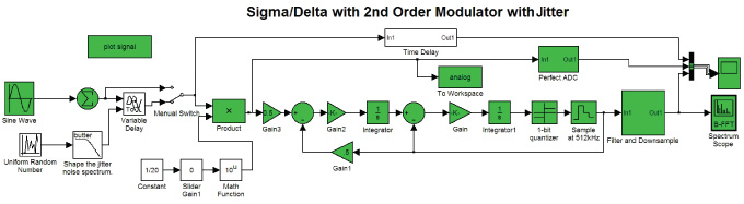
FIGURE 2 Second order sigma-delta ADC
Source: The MathWorks
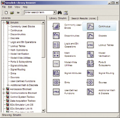
FIGURE 3 Libraries of analog and digital components
Source: The MathWorks
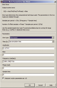
FIGURE 4 Adding behavior
How did we get that? Simulink has a set of libraries available to it, and you construct models through a drag-and-drop interface. So, progressing to Figure 3, this is the interface where we find that we can drop in an integrator, a source and a gain. Some of these components are analog, and some are digital—we can connect them together directly. Having connected them up, we will want some kind of output so we put in a oscilloscope.
What if we want some behavior that is not the default behavior? Say we want a specific gain signal for example. To do that, you simply double-click on the gain block, and that opens up a dialogue box where you can enter the data (Figure 4).
What happens if you want some behavior that is not in an existing library? Then you can create your own Simulink blocks using C or Matlab.
As with many mixed-signal systems this model has a feedback loop in it, something that can cause significant problems for some simulation environments. Simulink copes with feedback loops naturally, and in fact that capability was built-in right from the start.
Variable time step handling
The temporal behavior of a typical analog system is fairly constant and predictable over long periods, but can sometimes undergo dramatic change for short periods. This presents a significant challenge when you want to run simulations.
A simulation can take very large time steps. That will save on computational power and time, but also means the simulation is likely to miss capturing the system’s behavior when it changes radically over a short period of time.
Alternatively, it can take very small time steps throughout. This captures rapidly changing behavior, but is also unnecessarily lengthy and computationally very expensive.
Simulink offers a third approach. Here, the simulation takes a variable time step, so that when the system is changing very rapidly, it sets a small time step and when the system is hardly changing at all it sets larger ones. This provides the balance between accuracy and computational efficiency.
Our ADC system has different data rates, something we can see by turning on the rate display as shown in Figure 5. Different colors show different data rates, with variable time step branches in black (analog components), and the different fixed steps in different colors (the digital components). As you can see, the model consists of multiple different time steps. Note how blocks operating at different rates are directly connected together.
If various time steps are being used in the simulation, how can we control them? Figure 6 shows the Simulink configuration menu where the time steps are controlled. This is a simple interface where the default options are the best in almost all cases. If we have analog components in the model we can select a variable time step, or if the model is wholly digital we can select a fixed time step.
If you need even greater control, you can change the solver, you can change the minimum tolerances, or you can change the maximum step sizes. All those advanced options are there. But if you just want to get something akin to a ballpark option, you can use the default options.
Executable specifications
If this kind of system-model is developed early on, then it can be used as an executable specification. Paper specifications are ambiguous, but an executing system is not. An executable specification in the form of a functioning system model enables geographically separated groups to reason about the behavior of the system and to understand how their component has to fit in to the overall system.
The bottom line
This design process enables us to get something up and running very quickly—we can find an accurate behavioral solution rapidly, much more quickly than is usually the case in AMS design.
Lastly, before we start putting all this together, we must note that while efficiencies in modeling and temporal analysis are important, there may be points where the granularity of circuit-level simulation is required. That is still available. You do not give it up when you move to a more system oriented flow, as we will now go on to discuss.
In the real world
Semiconductor company IDT New Wave was looking to improve its mixed-signal simulations. Their previous method was based purely at the circuit level, and it used to take days to run. The feedback loops in the design slowed the simulation engine down greatly. In addition to the variable time step solver, Simulink has the capacity to deal with algebraic loops, so IDT was able to use the tools and concepts described above to shorten its design cycle and identify algorithmic flaws earlier in its flow.
Source: The MathWorks
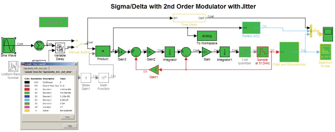
FIGURE 5 Exposing the clocks in the ADC
Let’s summarize the benefits of using this type of approach. Using traditional design models, you can easily become entangled in the details of the analog components, and because of the cost of changing these models, can only examine a few different architectures. By taking a more abstracted approach, you can quickly evaluate a wider range of architectures. This more comprehensive exploration will give you confidence that your final decision is the ‘right’ one. Its rapid design capability also substantially reduces the risk of serious errors being found later in the design process and helps avoid respins or late-stage ECOs.
Linking tools and teams
Effective communication between analog and digital engineers has a tremendous impact on your flow’s efficiency once you move beyond behavioral evaluation toward actual implementation. Consider again Figure 1. Our simplified design flow shows no obstacles between the digital and analog groups, but in many cases there might as well be a brick wall. One semiconductor company told us it was so hard to get the analog and digital teams to communicate during design that they waited until they had a test chip from the foundry before testing the analog-digital interface.
The problem is not that these teams inherently dislike one other or do not appreciate the need for constant and productive communication; rather it lies in the lack of a common language.
Source: The MathWorks
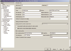
FIGURE 6 Controlling the time steps
A digital engineer will at some point need to check that his design works with the design of his analog counterpart. So, he will ask his colleague to supply some test source, and that colleague will then run an analog design tool to output the necessary data. The data will almost certainly not be in a format that the digital tools can read. So, it will need some translation—and maybe a graduate engineer at the company has written some Perl scripts to do that. But, if there are 10, 20 or 30 seconds of data, it will be an enormous file and it is going to take time to process. Finally, though, the digital engineer can read the data into his work and get some answers.
Then, inevitably, the analog designer asks his digital colleague to return the favor and we go through the process again, but in the other direction.
There are several problems with this.
- It is slow. The time taken for simulation is compounded by the time taken translating and transferring data.
- It is cumbersome. Simply moving these enormous files around can be awkward. I have worked on a project where even with a fast link between two different sites in different countries, translation and processing meant that it was still quicker to burn DVDs and send them via a courier than to transfer the data online.
- It is very static, and this is the biggest problem of all. We cannot simulate the dynamic analog-digital interaction. If something in the simulation causes the modulation scheme to change, this will affect the analog components, and this change in the analog behavior may in turn affect the digital parts of the system. This kind of interaction cannot be studied using a file-based simulation method.
Both analog and digital designers need a common platform that removes these obstacles. This is where Simulink shows its capabilities. Not only can it simulate mixed-signal systems, but it has links to tools from other vendors for implementation and those other vendors have links from their products to Simulink.
In the digital domain, there are co-simulation links from Simulink to Mentor Graphics’ ModelSim, Synopsys’ Discovery and Cadence Design Systems’ Incisive. In the analog domain there are links to Cadence’ PSpice and Spectre RF, Synopsys’ Saber and others.
Co-simulation can be defined as the use of bidirectional runtime links between Simulink (and, for that matter, Matlab) and other tools. You can run the two tools together and exchange data in real time as the simulation progresses. Basically for every model time step you take, you exchange data. This means you can see the dynamic changes of behavior between the different models in the system. In essence, we thus have Simulink acting as the common design platform. From a behavioral description, you can now call down from a higher level abstraction to a detailed implementation in a tool from another vendor—all at run time.
Let’s take an example. A real RF receiver will introduce distortions into a signal that affect the behavior of a digital receiver. By making a call from Simulink to, say, ModelSim, a digital engineer can see straightaway how his digital receiver implementation copes with those distortions and decide if the result is within tolerance or if the design needs to be changed. Meanwhile, an analog engineer can call from the analog portions of his system in Simulink to see implementations running on SpectreRF. He can thus see how his designs perform within the context of the digital simulation in Simulink.
In both scenarios, Simulink is acting as a test harness, giving analog and digital designers confidence that the interplay between their work will actually meet the needs of the final system, and providing that information much more quickly and dynamically.
- This is faster. There is no need to swap files. We can use just one model and isolate pieces that we want to test for by calling directly down to other appropriate software.
- It is easier. There are no huge data files floating around. In fact, all that’s ‘floating around’ is the common and agreed Simulink model.
- It’s very dynamic. We can almost immediately see how changes in the digital system affect the analog system and vice versa because they all execute in the same model at the same time. Two vendors’ simulation environments work together to enable you to study your environment much better.
As well as the links cited above, Simulink also has links to test equipment that enables hardware in-the-loop testing, and brings to bear the power of Matlab for data analysis to be used to interpret the test results. Simulink has links to test equipment from manufacturers such as Agilent, Anritsu, LeCroy, Rohde & Schwarz and others.
We have moved from a very high level of abstraction into the implementation world by using Simulink models as the test harness for analog and digital designs. Reusing system-models in this way enables us to find errors much earlier in the flow.
In the real world
Realtek was developing an audio IC and had the same need to improve intra-team communication while streamlining the project’s life cycle. Using Simulink as a common design platform, they were able to get the teams to share data from early in the design process and this made it far easier for them to work together. The teams could speak the same language and use the same test environment. Notably, the resulting design took a very high market share in its first year of release.
A coherent design process
We are now ready to bring all these elements together in a single flow and create the coherent design process we discussed earlier.
Simulink allows you to model multiple domain systems in the same model: continuous time, discrete time, discrete event, finite state machines, physical and circuit models. So, one simulation can include digital hardware, analog and RF hardware, embedded software and the environment, with each part interacting with the others as appropriate.
Using Simulink, you can quickly create an abstract behavioral model of a system. This enables you to very rapidly choose between different system architectures, so giving you greater confidence the design will work on a first pass.
Moving onto implementation, analog parts of a model can be removed and replaced by co-simulation links to an analog design tool. The analog implementation team can thus continue to use its existing design tools, and also dynamically test the behavior of its analog subsystem against the dynamic behavior of the digital subsystem.
Similarly, the digital engineers can replace the digital portions of the model with co-simulation links and hence test the digital implementation against the analog behavior of the system.
This approach flushes out interface errors much earlier in the design process.
The final step in this process is the reuse of the system-model as a golden reference against which to compare the delivered hardware. This involves connecting Simulink to the test equipment and to the analysis and interpretation of the captured test results.
In essence, we are reusing the same system-model again and again as we move through the design stages.
Summary
By introducing abstraction into the design process we enable AMS designers to find a working architecture much more quickly than they could previously. We’ve linked different groups in the design process via a common design platform. And we’ve cut down on development effort by reusing the same model through the design process.
In more specific terms for AMS designers, we have shown how they can gain practical advantages by taking a more abstract system-level view, and how this same process can be used to improve the communication between analog and digital engineers.
The MathWorks
3 Apple Hill Drive
Natick
MA 01760
USA
T: +1 508 647 7000
W: www.mathworks.com
