Automating test from IP to SoC levels with portable stimulus
This introduction to the new Accellera standard includes a demo of portable stimulus in use to fully verify a DMA engine.
What is portable stimulus?
A lot of energy has been invested over the last few years developing techniques to improve the productivity and quality-of-results of design verification. These techniques — such as constrained-random transaction generation, functional coverage, and the UVM —have provided dramatic improvements but mostly at the block level. The verification challenge continues to grow at the subsystem and SoC levels. So, a new approach is called for.
Both commercial and in-house tools have been developed to deliver the broader increases now demanded in productivity and efficiency. Mentor’s Questa inFact is one example. It raises the level of abstraction (boosting productivity), increases test-generation efficiency, and can be applied across a wide variety of verification environments. Such work has been accompanied by important work at the standards level.
As interest in bringing automated tests beyond transaction-oriented block-level environments has increased, so has interest in having a standardized input-specification language with which to specify these tests. In response, Accellera launched the Portable Stimulus Working Group (PSWG) to collect requirements, garner technology contributions, and specify such a language, one that can be used to specify test intent across a variety of verification platforms. Mentor participated in and helped drive the work of the PSWG, contributing its technology and expertise to the standardization process.
The goals of portable stimulus are illustrated in Figure 1. Specifically, the concept is to have a single description of test intent (the portable stimulus description) that can be targeted for IP-level, subsystem-level, and SoC-level verification and that is capable of implementing intent in a way that is appropriate to whatever verification engine is being used.
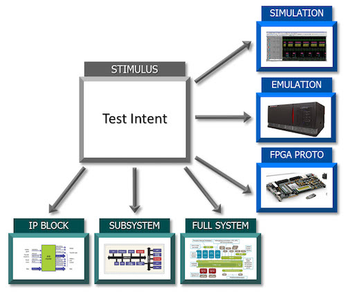
Figure 1. The goals of portable stimulus (Mentor)
In addition to describing the goals of portable stimulus, it is also important to emphasize what it is not. A portable stimulus description does not force all descriptions to be at a single level of abstraction or force all test intent to be done in a single, limited way. As we will see, there are multiple elements to the portable stimulus specification currently being developed by the PSWG. Users have the flexibility to describe their test intent in the way that is most natural to their verification task.
It is also important to note that it is the creation of highly-efficient automated tests that the PSWG seeks to make portable. Portable stimulus is not just a collection of ‘lowest common denominator’ techniques that can easily be supported across all verification engines.
Further, the Accellera Portable Stimulus Specification (PSS) is not intended to be a replacement for existing procedural languages, such as C/C++ or SystemVerilog. The reuse of code in existing languages is critical, so the Accellera PSS provides mechanisms to reuse behavior described in those and other languages.
Portable stimulus fundamentals
Portable stimulus seeks to raise the level of abstraction and enable the automated test of complex scenarios that emerge in subsystem- and SoC-level verification. However, the PSS under development by the Accellera PSWG builds on the base of constraint-based, transaction-level verification that is already well understood and widely deployed. On top of these foundations, the Accellera PSS provides features squarely targeted at enabling complex SoC-level scenarios to be captured by the user and efficiently realized.
Thus, the Accellera PSS supports random and non-random data fields and structures, familiar SystemVerilog constraints, and inheritance patterns familiar from object-oriented languages.
Building up scenarios in SystemVerilog is done by mixing constrained-random generation with procedural code. This introduces limitations, in terms of being able to reuse scenarios and customize them without changing the original code. The Accellera PSS provides an action as a primitive element of behavior, as well as a way to encapsulate complex behaviors in a way that can easily be reused and customized. Within complex actions, sequential and parallel execution of sub-actions, as well as repetitions over sub-actions, can be specified. The behavior within an action is specified in a declarative manner that enables a high degrees of automation and static analysis.
The Accellera PSS provides dedicated constructs for modeling the resource requirements of actions as well as data exchanges between actions in a scenario. This enables a user to describe the rules that bound legal scenarios, and allows a tool to automatically create complex legal scenarios based on those rules — much as data constraints specify the bounds of a legal transaction, enabling a constraint solver to automate generation of many legal transactions.
Portable stimulus at the block level
There is enormous benefit in applying portable stimulus to block-level verification environments. Portable stimulus tools require very effective and targeted test generation because of the requirement to efficiently generate tests for SoC-level environments. In a block-level environment, efficient test generation achieves functional coverage goals more quickly and finds bugs earlier. Users of Mentor’s Questa inFact, for example, have typically found that the tool is 10–100X more efficient than random generation at achieving coverage goals, enabling them to extend the scope of their coverage without increasing simulation resources.
Consider this example of a multi-channel engine for direct memory access (DMA). As is typical with this type of DMA engine, memory-transfer operations are characterized by a transfer descriptor that captures the transfer size, source and destination addresses, address increment settings, and detailed transfer options. At the block level, we want to comprehensively exercise combinations of these transfer-descriptor fields to verify the DMA implementation.
A simplified view of the UVM testbench surrounding this IP is shown in Figure 2. The DMA engine is exercised using a UVM sequence that programs registers within the DMA engine according to a DMA descriptor class.
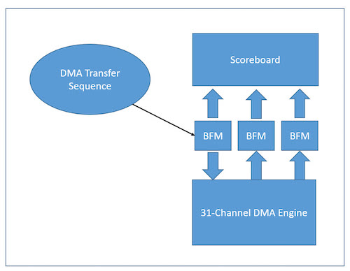
Figure 2. Simplified UVM testbench for DMA engine (Mentor)
Reusing SV constraints
The DMA descriptor class contains fields and constraints that define a valid DMA transfer. The ability to leverage this existing description from a portable stimulus description is important because an engineer has invested time to correctly capture the constraints and the rest of the environment is driven by this class. Fortunately, the transaction-level subset of the Accellera PSS overlaps with the SystemVerilog constraint subset to an extent that many SystemVerilog constraint-based descriptions can be converted to PSS descriptions.
Questa inFact provides an import tool for this purpose. A comparison of the original SystemVerilog class and the PSS struct is shown in Figure 3. Importing the SystemVerilog description and making it available inside a PSS description leverages the effort invested in creating the sequence-level description in SystemVerilog. This makes it easier to get started with PSS and ensures that the PSS description stays in sync with any changes made to the sequence item on the SystemVerilog side.
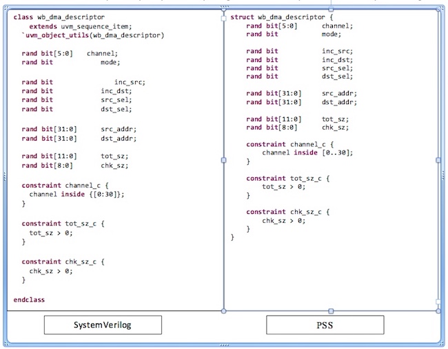
Figure 3. Comparison of SystemVerilog ‘class’ and PSS ‘struct’ (Mentor)
Specifying primitive operations
Now we will describe the most basic DMA operation: a DMA transfer. In a portable stimulus description, the data and behavior of an operation is encapsulated in an action.
As shown in Figure 4, an action is declared within a component. It encapsulates resources shared by multiple actions. At this basic block-level, we do not need anything special in our wb_dma_c component. Our do_dma action simply captures a random wb_dma_descriptor struct field. We will fill in the implementation details later.
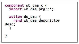
Figure 4. Declaring an ‘action’ within a ‘component’ (Mentor)
Describing scenarios
From a test perspective, one of the first things we might want to do is generate a series of single DMA transfers. We describe our test scenarios inside actions, just like our primitive operations. Since our scenarios are themselves composed of actions, we add an Activity Graph (keyword: activity) to specify the relationships between sub-actions (Figure 5).
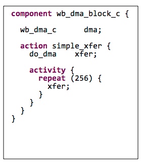
Figure 5. Adding an Activity Graph (Mentor)
Note that we declare our simple_xfer action within a component. This component contains an instance of the wb_dma_c component that declares the do_dma action. Our simple_xfer action simply runs 256 repetitions of the do_dma action (Figure 6).
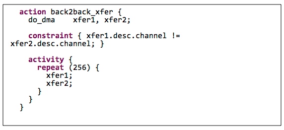
Figure 6. Detailed declaration of an ‘action’ within a ‘component’ (Mentor)
We might want to extend our testing a bit to perform two back-to-back DMA transfers, with the constraint that the channels used by the two transfers are different. This should provoke more-interesting activity within the DMA controller. Note how we can constrain the random fields of an action instance from above — something that is challenging to do with a directed-random sequence.
Specifying the environment interface
Thus far, we have not worried much about how our actions will connect to a UVM testbench environment. The type extension capability provided by the PSS makes it easy to layer in our interface to the environment without changing actions or components we have already described.
In our UVM testbench, stimulus is driven by a UVM sequence that generates wb_dma_descriptor sequence items. We will want to integrate our PSS description inside a UVM sequence and also have it generate wb_dma_descriptor sequence items — but with the field values selected by our portable stimulus tool instead of using regular constrained random SystemVerilog.
PSS packages are a great way to encapsulate environment specifics. We use one here (Figure 7) to contain the specifics of how our do_dma action will integrate with our UVM sequence. Specifically, we assume our sequence provides a task named do_item that accepts and executes a wb_dma_descriptor sequence item. The import statement specifies the signature of this external method.
Next, we need to specify how the do_dma action uses this imported method. The PSS provides exec blocks to specify the relationship between PSS entities and external code. The body type of an exec block specifies execution-time behavior (much as the UVM sequence body task does). In this case, we specify that the execution-time behavior of the do_dma action is to pass the wb_dma_descriptor field to the do_item task.
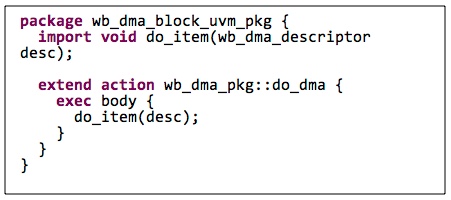
Figure 7. Using a PSS ‘package’ (Mentor)
And with that, we’re done! Our new PSS-drive UVM sequence can now drive the UVM testbench, with the advantage that we can much more efficiently exercise the DMA transfer modes (Figure 8).
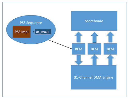
Figure 8. PSS sequence drives UVM testbench (Mentor)
Portable stimulus at the subsystem and SoC levels
At the subsystem and SoC levels, both what is verified and how it is verified change. Now instead of focusing on verifying the implementation of the DMA engine, we are more interested in how the DMA engine is integrated with the other blocks in the subsystem or SoC. What is also different, especially at the SoC level, is that we have an embedded processor, and we will want to drive at least some test activity with code running on that processor.
For a subsystem-level environment, we might start with a block diagram similar to that in Figure 9.
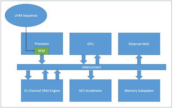
Figure 9. Subsystem block diagram incorporating DMA engine (Mentor)
The DMA engine is now in the context of a subsystem that includes a processor (stubbed out with a bus functional model) and other IP.
Bringing our PSS description forward into this subsystem/SoC environment can be done in two steps:
- Model the requirements of our scenario-level testing.
- Specify the new environment integration.
As mentioned earlier, our goal in this environment is to verify the integration with the other IP in the subsystem. To do so, we will run multiple, parallel DMA transfers. The first thing we will do is extend our dma_c component to specify the resources available — in this case, 31 DMA channels. Also, we will create a new action type that consumes a DMA channel and specifies its data-flow requirements (Figure 10).
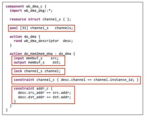
Figure 10. Extending ‘component’ and ‘action’ for subsystem verification (Mentor)
Our updated DMA component and action now specify:
- The DMA has 31 channel resources (using the pool of resources).
- Each DMA operation takes a source memory buffer and produces a destination memory buffer.
- Each do_mem2mem_dma operation (which inherits from do_dma) requires access to a DMA channel (using the lock field).
- The channel specified in the DMA descriptor must be the same as the channel assigned to the DMA operation.
- The source and destination addresses used for the DMA operation must match the source and destination memory buffer.
Filling in a bit more detail, we create an aes_c component to model operations on the AES block (Figure 11). Note that the do_encrypt action takes a memory buffer and that we have forced the address of input data to be the buffer address of the AES block. Constraints on the membuf_s input are bi-directional, so this constraint forces the DMA to target the AES device when a do_mem2mem_dma action sends data to a do_encrypt action. We also use a resource pool in the aes_c component to specify that only a single operation can occur on the AES block at a given time.
Finally, we specify a component to represent our system that specifies the available resources (DMA and AES blocks), and we specify a top-level action to perform parallel DMA transfers. Note that we have only captured the fact that we want to perform four parallel DMA operations.
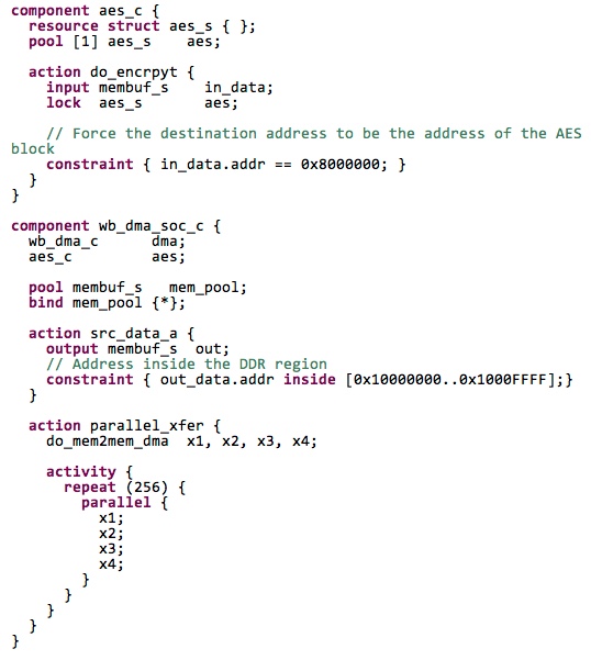
Figure 11. Toward a more detailed component (Mentor)
This is a partial specification: We do not specify where the data should come from, or where it should go. The PSS processing tool will infer and connect the appropriate actions to ensure legal scenarios are generated. Specifically:
- Each of the four parallel transfers occurs on a different DMA channel.
- Only one operation can target the AES block at a time.
Partial specification is a very powerful technique for generating complex test scenarios from a simple, concise specification.
SoC-level integration
In our subsystem-level environment, where DMA transfers are still driven by a sequence, we can reuse the same style of integration with the UVM environment that we did in the block-level environment. At the SoC level, our test will use utility functions written in C to program the DMA. In many cases, these utility functions will be the beginning of driver routines to later be used within an OS driver. Having our integration tests call these same utility routines provides an additional level of confidence in these utility routines. It also exercises the integration of hardware IP.
Just as with our block-level environment, we can extend our core PSS description to layer in the environment specifics. In this case (Figure 12), we describe the C API that we will call (wb_dma_drv_single_xfer), and we provide the definition of an exec block for the do_dma action that calls this API and passes values from the DMA descriptor.
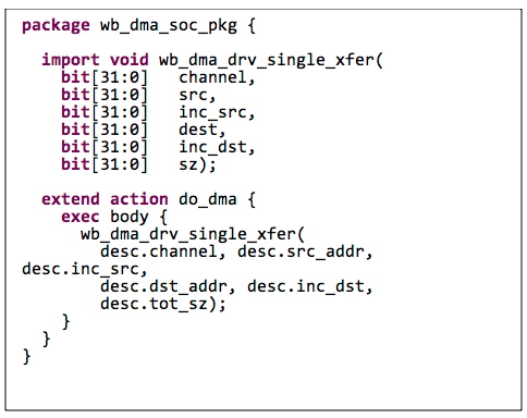
Figure 12. Extending the core PSS description (Mentor)
Boost productivity with portable stimulus
Portable stimulus tools help to raise the level of test description and enable modeling of scenarios that would be very challenging to create with directed and transaction-level constrained random tests. As a result, they enable the automated creation of more unique tests. As we have seen through the example used in this article, features of the Accellera PSS input specification enable test intent to be retargeted to different environments, while the core of the description remains environment independent. We have also seen that random fields and constraints can be easily brought in from existing SystemVerilog descriptions and that key components of the standard can be adopted incrementally, making it easy to get started.
So the next time you face a verification task that exceeds the capabilities of directed or constrained random tests, think about applying portable stimulus.
About the author
Matthew Ballance is a Product Manager and Portable Stimulus Technologist at Mentor, A Siemens Business. Over the past 19 years, he has worked in product development, marketing, and management roles in the areas of HW/SW co-verification, transaction-level modeling, and IP encapsulation and reuse. Matthew is a graduate of Oregon State University, and can be reached at matt_ballance AT mentor DOT com.
