Are you formally connected?
A large System on Chip (SoC) has tens of thousands of connections between modules and pins. Checking that these connections have been made properly is an important step in the verification process. This is often done initially with simulation, and then augmented using formal verification. Both methods start with a specification of all the required connections and are then meant to verify that all the inputs, outputs and paths between modules (i.e. Source and Destination nets) are connected as expected.
It is pretty clear what we want to verify, but what do we mean by ‘connected’? And, is ‘connected’ really what we want to verify? In a circuit we usually mean that two nodes are connected if there is a wire between them. But from a verification point of view that is not enough.
There may be one or many multiplexers in the path, so we are not dealing with a straight wire. We can get around this issue by defining that two nodes are connected only when the mux select pin has a value that makes it behave like a wire, i.e. if Enable is true, it implies that the Source is connected to the Destination.
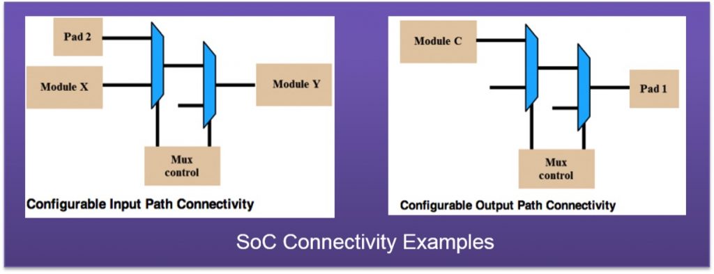
Figure 1 The connectivity of paths can be complicated by inline muxes (Source: Synopsys)
Even that is not a sufficient definition. We need a new definition of what connected means on an SoC.
Let’s formally define that a Source is connected to a Destination when these three conditions are met:
- They always have the same value when the Enable expression is true
- There is a structural path from Source to Destination
- The connection is directional from Source to Destination
If you don’t verify all three aspects of each connection pathway, the verification is not complete.
Simulation connectivity verification
When verifying connections using simulation, we drive a value on to the Source signal and observe it on the Destination signal. If we test enough values we become confident that the Source is connected to the Destination, but we have not proven that there is a connection, only that we observed the same values on the Destination as on the Source. If there are muxes in the path, we aso have to specify the values that make the Source value propagate to the Destination.
A connection in an SoC has a direction from input port to output port and in simulation, the direction of the connection is implicitly verified by the test methodology. If a value is driven on to the input (Source) it can be observed on the output (Destination), but if we drive a value on the output port it will not be reflected on the input port and the verification fails.
Connectivity verification in simulation does not verify whether a structural path exists, so we are only verifying the first and third requirement of the formal definition of ‘connected’.
Formal connectivity verification
Using formal analysis for connectivity verification gives a much stronger proof that the Source and Destination are connected. Instead of driving discrete values on to the Source and observing them on the Destination when the Enable expression is true, we use assertions to prove that they are connected.
In SystemVerilog an assertion of the following form would hold true:
assert property @(posedge clk) (enable |-> (source == destination)
This exhaustively verifies that every possible value on the Source net is equal to the value on the Destination net. This is a necessary but not sufficient condition for being formally connected. The assertion above would also hold true if both the Source and Destination were tied to the same constant value. For example, in Figure 2 below, out1 and out2 always have the same value – but they are not connected.
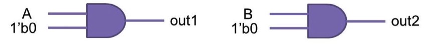
Figure 2 Out 1 and Out 2 always have the same value, but they are not connected (Source: Synopsys)
For this reason, SystemVerilog assertions are not a good way to express connectivity checks. There is nothing in the syntax that indicates direction or that a structural connection is required. CSV files or tcl commands are better suited to express the intended connections. A CSV file, as shown in Figure 3 below, has separate columns for Source and Destination, thus clearly indicating the direction of the connection.
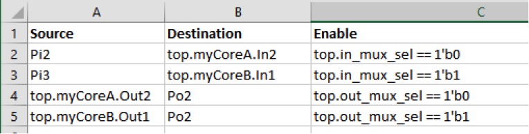
Figure 3 A spreadsheet may be a more effective way of defining an intended connection (Source: Synopsys)
The SystemVerilog assertion above doesn’t indicate direction and the formal tools need to explicitly check the direction of the connection. If the Source and Destination nets in the connectivity property are reversed the property should clearly fail.
Further, to be certain that two signals in the SoC are formally connected there must be a structural path between them. This means that it is possible to follow a path through nets, ports and gates from Source to Destination.
Determining whether a structural path exists between Source and Destination is easily done in formal analysis because it runs on a synthesized model of the SoC. This is one more reason why connectivity verification is more complete when using formal analysis than when done using simulation.
The existence of a structural path from Source to Destination is, by itself, also not enough for a connection to be considered formally connected. For example, if there is an inverter between the Source and Destination there is clearly a path through the inverter gate but the Source and Destination nets will never have the same value so the functional value check is always false.
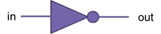
Figure 4 A structural path doesn't always imply a connection (Source: Synopsys)
Conclusions
It may not be enough to perform a functional value check on two nets to verify that they are connected. The existence of a directional, structural path is also necessary. Formal connectivity checking can verify all three conditions in the formal definition of ‘connected’, and so can completely verify all connections in a complex SoC. This application of formal verification technology is a clear complement to, and should be an essential part of, simulation-based functional verification flows.
Author
Anders Nordstrom is a Senior CAE, Verification Group at Synopsys. He is an ASIC design and verification professional with over 20 years of experience both as a design and verification engineer and from methodology development and customer support in the EDA field.
