Using VIP for cache coherency hardware implementations
Cache coherency implemented in hardware increases the verification effort. VIP-based strategies are described with particular reference to ARM protocols.
For multi-core SoCs, engineers have typically implemented cache coherency protocols in software. The shift to higher-performance, lower-power designs has led to an increasing preference for hardware implementations. ARM specifically has moved in this direction with the AMBA 4 ACE (AXI Coherency Extensions) protocol.
Hardware implementation nevertheless adds to verification complexity. Verification IP (VIP) enables engineers to properly validate such designs, but must include comprehensive support for the cache coherency protocol.
This article describes the background to cache coherency verification and the challenges it presents. It discusses the requirements for effective cache coherency VIP and how those are met by Synopsys’ SystemVerilog-based VIP suite and Reference Verification Platform (RVP).
Convergence drives development
Power-efficient, high-performance processing encourages the use of multicore chips incorporating separate processors, graphics, multimedia and networking cores. By using specialized processors, designers can meet power efficiency goals and create architectures that support short bursts of heavy processing alternating with long periods in standby.
Designing multicore chips is more challenging because:
- specifications are more complicated;
- software content is higher;
- interfaces are more sophisticated – and there are more of them;
- communication between cores adds to complexity; and
- architectures must balance the simultaneous needs of applications, both high performance and low power.
Then, there are the pressures from shrinking market windows and increasing development cost.
Cache coherency challenges
On-chip cache memory plays a critical role in multicore SoCs: the memory architecture is fundamental in determining system performance.
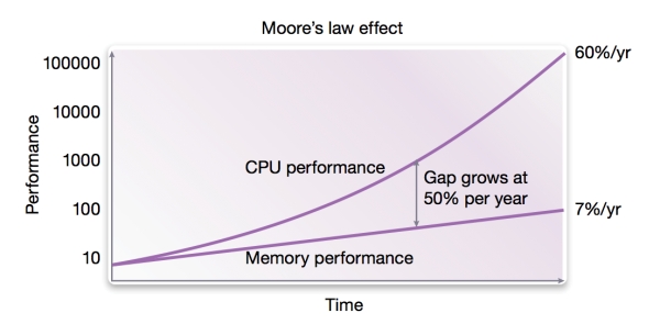
Historically, CPU speed has outpaced memory speed (Figure 1). This performance gap led to the use of on-chip cache memory in single-processor systems to prevent the CPU having to wait for instructions and data from memory.
Figure 1
Historical performance gap between CPU and memory performance (Source: Synopsys – click image to enlarge)
In a multicore SoC, individual cores must access and share data across the entire chip. Cache memories facilitate data sharing by fetching and storing data in local caches on-chip. This reduces the need to access off-chip memory which can require an order of magnitude more energy and often becomes a performance bottleneck.
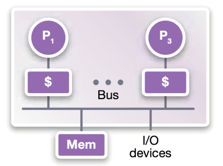
Cache coherency is about getting the right data to the right resources at the right time. Bus-based shared-memory (Figure 2) is the dominant architecture for multicore designs. In the scenario below, two processors, P1 and P3, share data (u) from the main memory (Figure 2a).
Figure 2a
Processors P1, P3 share memory on the bus (Source: Synopsys – click image to enlarge)
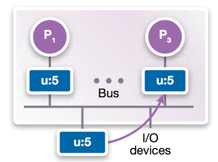
P1 and P3 initially read u=5 from memory and copy the value into each of the local cache memories (Figure 2b).
Figure 2b
Bus-based shared memory (Source: Synopsys – click image to enlarge)
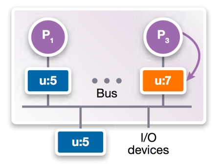
P3 performs an operation which results in u=7 being written into its local cache (Figure 2c).
Figure 2c
Bus-based shared memory (Source: Synopsys – click image to enlarge)
The cache coherency protocol determines how and when main memory and the P1 cache are updated to u=7. It does not become a problem that u=5 (and not 7) in the P1 cache until P1 needs it. The aim is to avoid going to main memory to retrieve the updated u.
Cache coherency protocols define a way of ensuring that all ‘simultaneous’ copies of a given memory location remain consistent across multiple caches. The system’s ‘consistency’ refers to when a cache sees a memory update; its ‘coherency’ to how other caches see a memory update.
The software-hardware pendulum
When CPUs had high clock speeds and spare processing capacity, design teams managed cache coherency in software using the processor. This provides more flexibility but less performance. Hardware provides better performance and power efficiency.
As demands on CPUs have grown with increased software complexity, processing bottlenecks have again become a problem. Architects have looked for functions they can implement in hardware to reduce demand on the processor. The software-hardware pendulum is swinging back towards hardware for cache coherency protocols.
ARM recognized that hardware cache coherency would free up valuable CPU cycles and improve power efficiency.
ARM’s cache coherency model
The AMBA 4 ACE protocol supports snoop-based and directory-based cache coherency protocols (snoop-based protocols account for most hardware-based implementations).
ARM’s fourth-generation AMBA protocol builds on successive improvements made since 1995. AMBA 4 phase 2, introduced in 2011, added ACE cache coherency to the existing AMBA AXI protocol. It provides system-level cache coherency, cache maintenance, distributed virtual memory and barrier transaction support. ACE is a natural extension to AXI’s bus-based protocol.
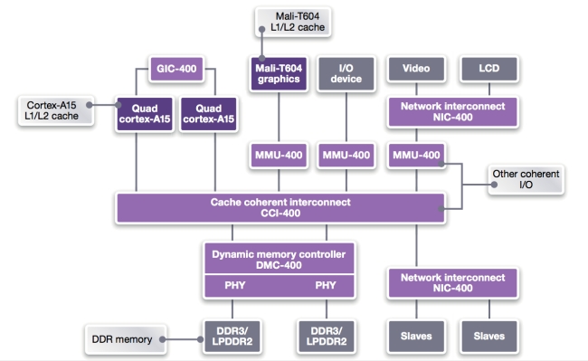
ARM’s core processors, graphics processors and other bus-based peripherals share their cache line values by implementing ACE. Figure 3 shows a CortexTM-A15 coherent system with CCI-400 Cache Coherent Interconnect and highlights a number of other core processors that require cache coherency, including the Mali-T604 L1/L2 cache, the main DDR 3/2 memory and other coherent IO.
Figure 3
ARM Cortex-A15 coherent system with CCI-400 Cache Coherent Interconnect (Source: Synopsys – click image to enlarge)
ACE protocol cache state model
ACE is based on a flexible five-state cache model designed to support cores that use a number of MOESI variations, including MESI and MEI. To emphasize that ACE is not constrained to the MOESI state model, ARM uses an alternative nomenclature (state names). Whereas early cache coherency protocols focused on functionality, ARM has built ACE for power and performance optimization by avoiding unnecessary accesses to external memory.
AMBA 4 also defines ACE-Lite. This is the preferred protocol for IO coherency and best power/performance. ACE-Lite masters can snoop ACE-compliant masters, but cannot be snooped themselves.
Table 1
ARM cache states and equivalent MOESI states (Source: Synopsys – click image to enlarge)
Design teams must follow some basic principles when using ACE:
- Lines held in more than one cache must be held in the Shared state.
- Only one copy can be in the SharedDirty state, and that is the one responsible for updating memory.
- Components and cores that depend on cache coherency are not required to support all five ACE states internally.
The system interconnect is fundamental to implementing ACE. The way that it coordinates the progress of shared transactions affects power consumption and performance.
For example, the interconnect can perform speculative reads to reduce latency and improve performance, or can wait until snoop responses have been received so it knows a memory read is required. This reduces power consumption.
ARM has developed the CoreLink CCI-400 Cache Coherent Interconnect to support up to two clusters of CPUs and three additional ACE-Lite masters.
Memory barriers and distributed virtual memory
Memory barriers help ensure correct operation in systems with shared-memory communications and out-of-order execution. ARM defines two types: the data memory barrier (DMB) and the data synchronization barrier (DSB).
The DMB prevents any re-ordering of loads and stores by ensuring that all memory transactions before the barrier appear to have completed before any transactions following the memory barrier.
When coherency extends beyond the MPcore cluster, the ACE protocol must broadcast the memory barrier on the ACE interface.
The DSB is useful when hardware interfaces besides memory are involved. It can be used to ensure that data reaches its destination when written to a DMA command buffer before initiating the direct memory access via a peripheral register.
Support for distributed virtual memory (DVM) in ACE allows invalidation messages to be broadcast.
These features are integral to the use of shared memory in multicore systems and must be fully supported by the verification environment.
The impact on verification
Multicore SoCs with cache coherency add complexity to verification.
Verification engineers must model the protocols in terms of cache line states and how changes to those states (transactions) are communicated to other coherent components across existing and additional AMBA AXI channel and signal interfaces.
Cache states, transactions and signals can be defined using object-oriented transaction-based verification methodologies such as VMM, OVM and UVM. These provide robust verification of multicore SoCs that use ACE through the application of:
- random stimulus generation;
- signal assertion and scoreboard-based checking; and
- functional coverage planning.
Verification engineers need a protocol verification environment that supports productive and robust debug.
Chiefly, the verification suite must support the full protocol topology, including models for the ACE master, slave and interconnect (or fabric IP) components.
Access to a comprehensive set of VIP that supports all components reduces verification time and improves confidence in the design’s correctness.
Design teams should be able to use VIP to create a fully functional AMBA design and testbench, including test cases, before RTL is available. They can then gradually replace the VIP models with RTL in any combination of master, slave and interconnect models. This allows users to start testing from a working testbench that is passing coherent transactions between the masters, interconnect and slaves before any RTL development is done.
The ability of the VIP to generate input stimulus for test is a major benefit in helping teams meet verification goals. To verify the ACE protocol, the VIP environment should provide pre-written libraries of input stimuli (i.e. UVM/OVM sequences or VMM scenarios) for the master/slave port level as well as the system level.
Examples of a master port-level stimulus sequence include ‘Blocking Write-Read’ and ‘Write Data Before Address’. Examples of a system-level stimulus sequence include either a single coherent transaction (‘WriteLineUnique’) or a multi-transaction sequence (‘Snoop During Memory Update’). The VIP environment should let users easily substitute other sequences and scenarios to reach verification goals.
The system-level VIP environment should offer control of port and system-level sequences using a virtual sequencer or multi-stream scenario generator. Combining all port and system-level sequences should enable coverage of all features in the specification. Designers should be able to easily create directed or random tests using the predefined sequences.
As well as generating stimulus, the VIP environment should support protocol checking and monitoring. For example, port-level monitors should be able to check that the protocol’s ‘IsShared’ and ‘PassDirty’ signals are correctly asserted in response to a ‘ReadClean’ transaction. System-level monitors should carry out system-level checks such as ensuring that no two masters have the same cache line in the ‘Dirty’ state.
Other useful checking features include:
- signal-level checks in port monitors;
- transaction-level checks in port monitors; and
- multi-port transaction level checks in system level monitor.
All checks should also be configurable.
Users want VIP that can provide coverage reports and planning features. They can then analyze improvements in coverage as the VIP executes more complex ACE protocol sequences.
Key coverage requirements include:
- signal-level coverage in port monitors;
- transaction-level coverage in port monitors; and
- system-level coverage.
All coverage must be built-in and configurable. It should include feature-based coverage plans for master/slave and interconnect components which correlate to ARM’s specifications.
The environment should provide comprehensive debug capabilities, including visibility into source code for the most commonly used code users need to extend. VIP components should generate raw transaction-level data for use by debug tools.
Rapid model assembly
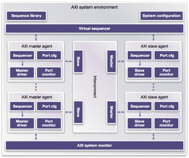
A comprehensive verification environment for ACE protocols should allow users to automatically create systems from VIP using a configurable top-level template, exploiting components such as those shown in Figure 4.
Figure 4
Synopsys Discovery VIP for AMBA ACE cache coherency protocol (Source: Synopsys – click image to enlarge)
Such a system-level environment will allow design teams to automatically create, instantiate, configure and connect multiple master, slave and interconnect VIP components by entering values in a system-level configuration object. Verification engineers can then build environments faster and with fewer errors than were they to configure the VIP manually.
Inside Discovery VIP for cache coherency
Synopsys’ Discovery VIP is based on Synopsys’ VIPER architecture. It has been engineered from the ground up for enhanced performance, configurability, portability, debug, coverage management, and extensibility. VIPER uses a layered architecture implemented only in SystemVerilog using best practices for all methodologies. It offers significant advantages in increasing protocol-based verification productivity.
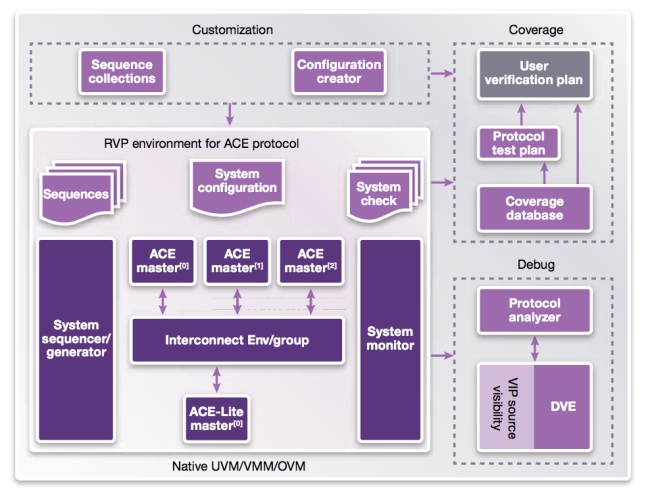
The Synopsys Reference Verification Platform (RVP) for the AMBA ACE protocol is a pre-configured environment that provides test cases using a constrained-random coverage-based UVM methodology within the VCS Functional Verification Solution (Figure 5).
Figure 5
Reference Verification Platform for AMBA AXI/ACE Protocol (Source: Synopsys – click image to enlarge)
Synopsys delivers the RVP in an initial configuration common to most ARM SoC designs: three master VIPs and one slave VIP (AMBA ACE-Lite) connected to the interconnect VIP. Users can take this base RVP and customize it as required by changing parameters in its configuration interface.
The RVP configures port and system-level stimulus generators to use a library of pre-written input stimulus as either UVM/OVM sequences or VMM scenarios.
Discovery VIP provides protocol monitoring and checking that is configuration aware; the user does not need to modify the system-level checks after updating the configuration.
The RVP demonstrates how design teams can debug AMBA ACE protocol errors at the signal or transaction level using the protocol-aware debug technology available in Protocol Analyzer, methodology-aware debug features in the Synopsys VCS Discovery Visualization Environment (DVE) and Springsoft’s Verdi, the open debug platform.
The inclusion of coverage planning and closure tools within the RVP means users can analyze coverage until they have met their goals.
Summary
A thorough understanding of the operation of ARM’s AMBA ACE cache coherency protocol helps design teams make informed choices when selecting VIP to improve the predictability of verification.
Synopsys’ Discovery VIP for AMBA 4 AXI and ACE protocols provides a 100% SystemVerilog-based VIP suite that supports the full protocol, including IP interconnect, and is easy to configure from a system-level environment.
A reference verification platform, such as Synopsys’ RVP, can help users quickly and efficiently verify multicore systems that incorporate cache coherency control.
Further reading
C. Thompson, Accelerated SoC Verification with Synopsys Discovery VIP for the ARM AMBA 4 ACE Protocol.
Synopsys Verification IP for AMBA 4.
A. Stevens, Introduction to AMBA 4 ACE [White Paper].
ARM, CoreLink CCI-400 Cache Coherent Interconnect for AMBA 4 ACE [Web Site] Retrieved from
Synopsys, A New Generation of VIP to Address the Growing Challenge of Complex Protocol and SoC Verification
About the author
Chris Thompson is a Verification Application Consultant on the Senior Staff at Synopsys.
Contact
Synopsys
700 East Middlefield Road
Mountain View
CA 94043
USA
T: +1 650 584 5000 or
+1 800 541-7737
W: www.synopsys.com
