Using assertions in ‘elemental analysis’ for airborne hardware development – Part One
This two-part article discusses the verification requirements of the RTCA DO-254 design assurance guidelines, including advanced methods for use on class DAL A/B designs. The first part provides a general overview. It also explains the original intent behind the concept of ‘elemental analysis’, how it is typically satisfied today with code coverage, and the limitations to this technique. Part Two will describe the additional use of assertion-based verification, and propose a method for using the technique to not only achieve elemental analysis but also support a systematic approach to satisfying a claim of robustness testing.
The RTCA DO-254 1 Design Assurance Guidance for Airborne Electronic Hardware requires additional advanced verification techniques for design assurance level (DAL) A or B devices.
The most commonly used is elemental analysis. It is intended to ensure requirements-based tests exercise the elements of a design sufficiently that they providing a measure of verification completeness. On HDL-based designs, this is typically performed by collecting code coverage metrics during the simulation of these tests, thus identifying which portions of the HDL code have not been exercised.
However, code coverage alone has a number of drawbacks as a metric for verification completeness. Another technique, assertion-based verification (ABV), is a more thorough and can also provide credit toward robustness testing.
ABV uses techniques that have been proven in various segments of the electronics industry during more than 20 years. Today, they are based on IEEE standards and supported by all leading simulators. Yet, ABV adoption in avionics is lagging. This is unfortunate. ABV can prove very powerful when used as part of a sound verification methodology. It provides much more verification and coverage assessment for only modest additional effort.
Verification under DO-254
The purpose of verification in a DO-254 program is to ensure that a design performs the function specified by its requirements. Verification is considered one of DO-254’s ‘supporting processes’: It is not a specific phase of development, but rather occurs throughout development. A key aspect of the design assurance DO-254 seeks is based on verification being performed at each key stage, from the earliest models to the final testing of the component in the system, so that it satisfies agreed-upon completion criteria.
In the most safety critical DAL A and B devices, verification must be carried out independent of the design. The verification work typically performed on, for example, an FPGA design would include simulation testing, and potentially other analysis (e.g., linting, clock-domain crossing analysis, etc) of the HDL code, static timing analysis of the synthesized netlist, back-annotated timing simulation of the netlist, lab testing, and final system testing.
All of these simulation tests are developed from requirements. They must therefore be thoroughly reviewed to ensure they verify that those requirements are met. But in support of design assurance, another question must be asked. Do these requirements-based tests sufficiently test all the functionality within the implementation? This is of fundamental importance because a design could accurately implement a set of requirements, but still contain other functionality that could in fact exhibit unintended and potentially destructive behaviors. Some sort of additional activity or metric is necessary to ensure that the requirements-based verification (RBV) activities sufficiently test all of the functionality implemented in the design.
This metric is typically offered by running code coverage during HDL simulation. This is done in support of the requirements for ‘Advanced Verification, Elemental Analysis’, described in DO-254 Appendix B.
Advanced verification methods
DO-254 Appendix B describes the additional design assurance activities that an applicant must perform on devices designated as DAL A or B (aka ‘DAL A/B’). Among these is the need for additional or ‘advanced’ verification. This will go beyond typical requirements-based testing, and the appendix offers several alternative verification methods, described below, as well as a broader set of strategies 2 beyond the scope of this paper.
1. Elemental analysis
‘Elemental analysis’ is not a broadly-known design methodology. Rather, the term is specific to DO-254 and refers to the verification of testing completeness. The objective is to ensure that all ‘elements’ of a design are actually exercised in the requirements-based testing that the scheme mandates.
The term ‘element’ was chosen because the scope of DO-254 was originally quite comprehensive, and an ‘element’ (or the lowest level ‘thing’ that an engineer from a particular discipline would use to create the design) could vary from chip to board to system level, and could also change in terms of the technology according to the level of design abstraction. So, in the context of FPGA/ASIC devices that are typically designed in HDLs, an element may be considered a statement or some other structure within the code. Thus, the most common metric for determining if these coding structures are exercised by simulation is called code coverage.
Running code coverage (in conjunction with a thoroughly reviewed and simulated requirements-based test set) has become the de facto standard method for meeting the objectives of elemental analysis. But as shown below, this does not necessarily mean coverage provides the highest level of design assurance. Moreover, just because one method has been used repeatedly, other methods may be better suited. After all, elemental analysis describes a goal, but does not say how it could or should be met. How to meet elemental analysis technically should be left up to the DO-254 applicant, who should examine all potential methods and choose one best aligned with the goals of design assurance or a demonstration that a device performs its intended function (with no anomalous behaviors). We explore this below.
2. Safety-specific verification analysis
The second type of advanced verification listed in Appendix B is ‘safety specific verification analysis’. It uses analysis techniques to identify areas in the design that could exhibit behaviors that jeopardize system safety. The aim is to check for not only intended-function requirements verification, but also anomalous behaviors.
Like elemental analysis, this method is not defined in terms of specifically how this can be achieved. Instead, it encourages applicants to propose a method to determine the safety-sensitive portions of the hardware, stimulate them sufficiently to expose any issues, and then observe the results to ensure the device does not behave in any anomalous way.
3. Formal methods
The third method of Advanced Verification listed in Appendix B is ‘formal methods’. This is one of the most misunderstood areas of DO-254. Formal methods are simply static verification methods that use mathematical analysis to prove design behavior. They are very powerful and represent the only way of undertaking exhaustive verification and finding anomalous behaviors in today’s complex devices. Formal methods are described in more detail towards the end of this paper.
The intent of elemental analysis
The intent behind elemental analysis is fairly straightforward. The idea is to create completion criteria for verification testing. Elemental analysis is an attempt to answer the question, “When are we done with verification testing?”
Fundamentally, the technique is based upon a foundation of requirements-based testing (RBT). Let’s explore this further. RBT basically says, “Create independent verification tests with respect to requirements to verify the design meets these requirements.”
The philosophy of DO-254 is that RBT is good enough for DAL C functions, but additional confidence in the function’s implementation is needed for DAL A or B functions. The key concern is whether or not the testing of the hardware item was complete (with the understanding that typical RBV may not completely test the implementation). That is, are all the requirements implemented in the design truly exercised by the testcases provided? Certainly human reviews of the testcases and the design add confidence that the tests and design are correct, but when a design must meet the requirements of Level A/B, more metrics are needed to provide additional confidence. Elemental analysis is a method intended to provide this extra confidence.
Why can the RBT be incomplete? Why would additional verification completeness metrics be needed? Let’s list a few possibilities:
- Inferred requirements. Designers frequently make implementation decisions. Sometimes these include the implementation of logic that should have been specified as a requirement but was overlooked. As a result, no requirement exists and no RBT exists to test this functionality.
- Inadequate RBT Testcases.
- Missing requirements.
- Untestable features.
- Extraneous features, or unused features of reused design code.
Elemental analysis is not intended to cause more test cases to be generated merely to satisfy the coverage criteria; it specifically discourages the creation of test cases that are not based on the requirements. The method is intended to measure the completeness of RBT from the perspective of the implementation by accounting for testing of the elements of the design.
Elemental analysis is a process that provides confirmation of the completeness of the hardware verification from a bottom-up perspective. Every functional element within the complex hardware is identified and verified using verification test cases that meet the RBV objectives of DO-254. The analysis may also identify areas of concern that need to be addressed by other appropriate means.
The process of performing elemental analysis is conceptually straightforward: if we assume we have perfect requirements on a project, and a perfect verification completeness criteria metric, then we can simply do the following:
- Create all verification tests to verify all requirements, independent of the design implementation.
- Simulate this suite of tests on the design, capturing completeness using the perfect completeness metric.
- Analyze the results of the verification completeness metrics.
We can then determing that any element in the design that is left uncovered is one of the following:
- Unnecessary code (that should be removed).
- Necessary code that lacks a requirement and associated test (so the missing requirement and associated test should be added).
- Some kind of anomaly that needs further analysis and possibly needs to be excluded (such as some types of error scenario recovery or test-only logic).
A Metric for Verification Completion
As stated, to meet elemental analysis, every functional element within the complex hardware is identified and verified using verification test cases that match the requirements-based verification objectives of DO-254.
This implies two things:
- A definition of ‘functional elements’.
- A verification completeness criteria metric to measure verification completeness of these functional elements.
Currently, when a DO-254 applicant with an HDL-based design claims evidence toward elemental analysis, the applicant typically provides the following:
- A definition of ‘functional elements’ as individual statements or constructs within the HDL code itself.
- Simulation-based ‘line coverage’ or statement coverage showing that all the statements in the associated HDL code were exercised by the RBT testcases provided (or other analysis evidence for any HDL code showing lack of coverage). This is sometimes augmented by additional more rigorous code coverage metrics such as branch coverage, condition coverage, expression coverage, finite state machine coverage, and sometimes even toggle coverage 3.
All these code coverage metrics work in a similar way. They examine a piece of RTL code in isolation from all other RTL code and determine if the RBTs stimulated that piece of code. How that code interacts with other code and whether those interactions were tested are not addressed. This is an important limitation.
How did we end up in a situation where the default functional element was a small piece of the HDL code? Initially, an ‘element’ referred to an item in a schematic-based design. In a schematic, an element is relatively straightforward: It is a gate or other library element that the engineer places in the design. The term was chosen as a synonym for ‘component’ to represent the tangible aspect of hardware design but avoid confusion with the idea of a ‘component’ one would order from a catalog or put on a parts list. Together, these elements create the full design.
However, as design techniques evolved to include synthesis, this led to uncertainty over what to call a ‘functional element’ in a synthesizable RTL based hardware design. DO-254 states an element is based upon the level the designer used to enter the design, in this case, VHDL or Verilog HDL code. So, DO-254 hardware applicants adopted code coverage techniques toward elemental analysis.
This makes sense in some respects. HDL-based code coverage metrics 4 are built into most popular commercial HDL simulators and are quite easy to turn on and use. The commercial electronics industry has been using code coverage metrics successfully for years to help identify untested HDL. And HDL looks like software, so it is easy to think that hitting all the lines of code will fully exercise the design.
But it is also easy to overstate what these coverage metrics are revealing. For a given piece of code, a lack of code coverage clearly shows a portion of the design has not been fully tested. However, most experienced engineers know that designs showing high coverage may not be fully tested. This is due to the concurrent nature of hardware designs set against the sequential isolated view of even the most rigorous code coverage metrics. DO-254 (Section 3.3.1.1) also stresses this point, although perhaps not as clearly as it should.
Basically, in simulation-based code coverage, a single aspect of HDL code is exercised (and marked as covered) when that piece of HDL is exercised in isolation. This happens regardless of the behavior of the rest of the design. In addition, these code coverage metrics do not take into account whether or not any anomalous behavior that might have been exercised can be observed at an available observation point.
This issue can be easily overlooked, even for people with a background in digital hardware design. Let’s explore this further using a simple example. Consider the following simple design (Figure 1). The red arrow coming from the top register, shows the design error, manifested as erroneous data that sometimes gets loaded into a register, then is sent through two multiplexers, and into a downstream register when both multiplexers are selecting the ‘0’ port):
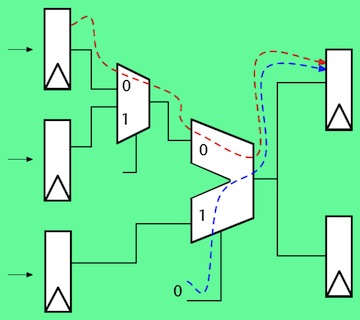
Figure 1. Design error example (Source: Mentor Graphics)
The HDL code to describe this design is simple, and code coverage results for this code are easily analyzed:
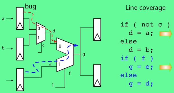
Figure 1a. Design error example (Source: Mentor Graphics)
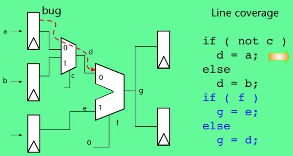
Figure 1b. Design error example (Source: Mentor Graphics)
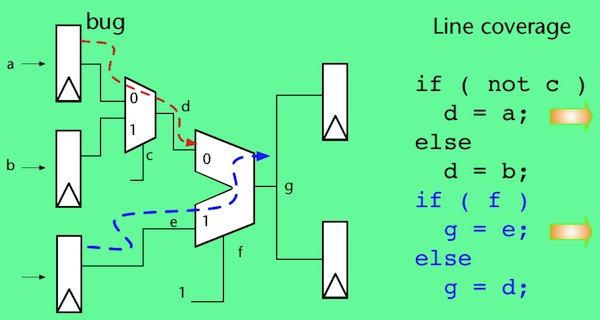
Figure 1c. Design error example (Source: Mentor Graphics)
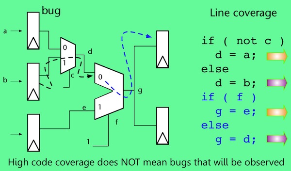
Figure 1d. Design error example (Source: Mentor Graphics)
The design was fully covered by code coverage (Figures 1a-1d), and no errors were detected, indicating the design is error-free. But there is an error in the design; the test even stimulated the error. The problem is one of propagation and observation.
To be clear, testcases should use a variety of data values, including boundary conditions, and any other known variations to try to fully test the design. However, even with this variety of input stimuli at least some design errors like this will not be detected using RBT and code coverage.
Even the best code coverage metrics are unlikely to flag a case like this because several different parts of the design have to be exercised in specific ways simultaneously for the erroneous result to be propagated to an observable point. Code coverage simply does not examine simultaneous behavior across multiple parts of the design, not even when more rigorous coverage metrics like focused expression coverage are used (this is the hardware equivalent of software’s multiple condition decision coverage (MCDC)).
One well-respected verification study 5 showed that, even with 100% coverage, only 72% of the potentially erroneous behavior was observable.
This issue is further exposed when we examine where design errors tend to exist in digital hardware designs, and when anomalous behavior is the most difficult to detect. A study done by Ted Scardamalia from IBM in the 1970s examined design error densities for various classes of designs (i.e. which parts of a design are more likely to contain an error). It found that data stream blocks will contain about two design errors per 1,000 gates, but concurrent blocks will contain about 10 design errors for every 1,000 gates.
This study shows a relationship that still holds true in today’s HDL designs 6: Designs with concurrency (typically designs with control logic) will contain on average 5x more design errors than datapath-only designs (designs with minimal control logic) (Figures 2 and 3 below).
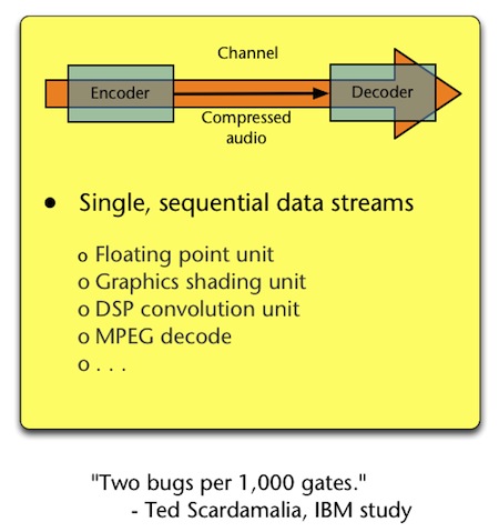
Figure 2. Example sequential data stream (Source: IBM)
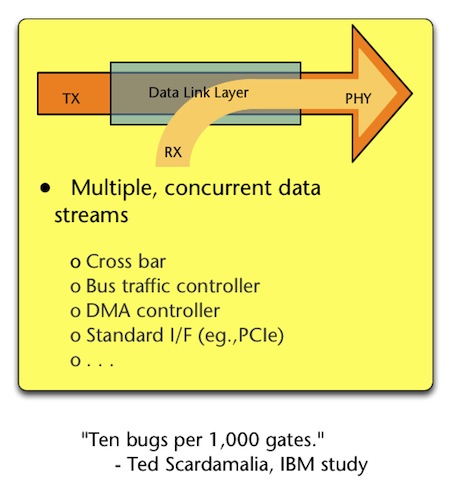
Figure 3. Example concurrent data stream (Source: IBM)
This means that designs containing concurrency:
- have five times more design errors to begin with: and
- are such that engineers are less likely to observe the erroneous behavior with ‘complete verification’ as measured by code coverage metrics.
Any design with any degree of complexity will contain control logic and concurrency.
This discussion is not intended to argue that hardware code coverage metrics should not be used, or that any existing DO-254 DAL A/B design previously deemed ‘compliant’ using code coverage as evidence toward claiming elemental analysis is inadequate. However, it clearly demonstrates weaknesses in code coverage as a single metric toward answering the question, “Have we exercised all of the design, thoroughly?” (the goal of Elemental Analysis). As a result, this clearly shows that other types of analysis and coverage techniques should be considered toward meeting Elemental Analysis.
Providing a better metric for verification completion
Before discussing a better metric, it is important to state that there is no Holy Grail of metrics. This is debated among even the most experienced verification engineers. That said, at the highest conceptual level, most engineers agree that we need a verification completion metric that provides confirmation that the design:
- is doing everything it is supposed to do when it is supposed to do it;
- is not doing what it is not supposed to do;
- has exercised all the important corner case behaviors (considering concurrency) with correct responses; and
- has enough observability to allow any design errors or anomalous behaviors to be caught.
A well designed and carefully reviewed RBT addresses the first two of those criteria, but only for the specific requirement for which it was created. Because an RBT is created independent from the design, there is absolutely no guarantee that even the best of them will meet the third and fourth.
Code coverage (even the most advanced code coverage metrics previously discussed) will not directly perform any of these four steps. If we take each in turn, it should be obvious why:
- Is the design doing what it is supposed to? Obviously code coverage does not measure correctness; only that whatever code is present was stimulated.
- Is the design not doing what it is not supposed to do? Again, code coverage does not judge the correctness or incorrectness of the code behavior; only whether or not it was exercised
- Are we exercising the important corner case behaviors with correct responses? Certainly some corner cases are specific to small isolated portions of the design, and these can be shown as exercised by code coverage. But, as discussed earlier, many important corner cases involve multiple concurrent portions of the code to be activated at the same time. Code coverage does not measure this. And, in addition, code coverage has no ability to judge the correctness of the response.
- Does the design have enough observability to detect any anomalous behavior that might have been stimulated? As shown earlier, code coverage does not consider whether any behavior can or has been propagated to an observable point.
Commercial chip manufacturers faced this dilemma years ago, and eventually settled upon a methodology called assertion-based verification (ABV) to better identify design errors in their designs, and to improve overall verification quality and efficiency. We talk more about ABV in part two of this paper.
References
1. RTCA DO-254, Design Assurance Guidance for Airborne Electronic Hardware, RTCA Inc., Washington, DC, 2000.
2. Beland, Steven C. and Barbara A. Bonjour, “Functional Failure Path Analysis of Airborne Electronic Hardware“, Digital Avionics System Conference, IEEE/AIAA, 12.
3. Toggle coverage is a particularly poor choice for a coverage metric on RTL HDL code, but this discussion is beyond the scope of this paper.
4. Various code coverage metrics are typically available, including Statement, Branch, Condition, FSM (Finite State Machine), Focused Expression (FEC – Similar in concept to MCDC in software coverage), and Toggle coverage
5. Fallah, F. S. Devadas, K. Keutzer, “OCCOM: Efficient Computation of Observability-Based Code Coverage Metrics for Functional Verification”, 35th Design Automation Conference (DAC), San Francisco, June 1998.
Contacts
Mentor Graphics
Worldwide Headquarters
8005 SW Boeckman Rd
Wilsonville
OR 97070-7777
USA
T: 1 503-685-7000
W: www.mentor.com
Boeing Commercial Airplanes
P. O. Box 3707
Seattle
WA 98124
USA
T: 1 206-655-1131
W: www.boeing.com/commercial

Excelent article with detailed explanation.