Vehicle ethernet adds to IP virtual reference kits for board design
Automotive ethernet is the latest virtual reference design platform to be added to the family of models developed by Cadence Design Systems to support the design of the company’s media-access and physical-layer IP cores into full systems.
Using a combination of the company’s Sigrity analysis tools and Ibis models of the IP and key components in the signal path, the aim of the virtual reference designs is to let designers work out whether a proposed PCB stack-up as they optimize for cost is likely to work and then help put it into action.
“All our sales guys get that question: ‘will your IP work in my environment?’” said Heiko Dudek, field engineering group director at Cadence in Europe. “It’s not a very easy question to answer. Even if you follow the guidelines. But if you want to make tradeoffs. How do you explore all of that? You can have an environment that explores those architectural possibilities.
“The next step is once you are done with the design, get the question answered: does this work? Simulating architecture is one thing but we need the return paths – does everything still work with the combination of components and PCB traces that we have? And if it doesn’t work, how to debug it?”
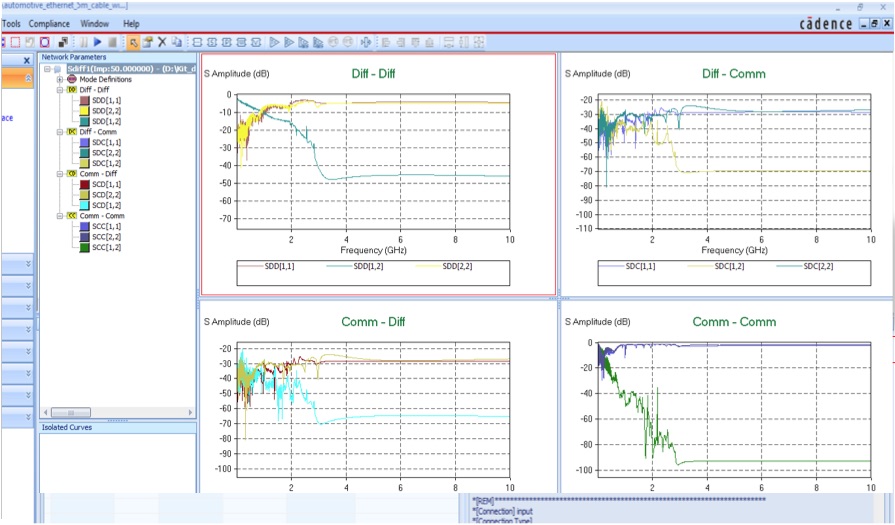
Image S-parameter curves generated by the platform can be used in compliance checks
Dudek said the models provided of the Cadence physical-layer IP cores are silicon-correlated Ibis models that conform to their behavior on test chips run on a variety of multiproject wafer and shuttle runs. “This is something hardly anyone does,” Dudek claimed. “They are both power-aware and silicon-correlated. We model the power-integrity path.”
The Ibis models are implemented using the algorithmic modeling interface. These are bundled into reference designs that either focus on a specific market, such as automotive ethernet, or come in two or three versions to suit different applications. “We figured that one reference design would not do the job. One is aimed at high-reliability applications, the second is cost-optimized entertainment systems, and then one for mobile where everything needs to be low power.
“Finally, we have compliance checks based on the relevant standards definitions. The tool generates HTML documents to tell you where you passed or failed the compliance checks.”
Likelihood of success
Dudek said the initial analysis will provide an estimate of how likely the design is likely to succeed using specified packages and PCB layer count. “With a BGA and four-layer PCB, the tool may come back with a 95 per cent chance of success, and this is the power/ground setup you should pick. It may change to 100 per cent for a six-layer PCB.
However, rather than increase layer count, designers will look to find ways to trim the layer count and use cheaper packages to keep costs low. The signal-integrity analysis can probe the different tradeoffs to see what works. “You may need the PHY to be L-shaped on the die and you need to route some signals over a longer distance, but maybe it is possible to compensate for that in the package using the redistribution layer.”
Dudek said before the technology was fully developed, Cadence hired a consultancy to make physical reference designs for some of the IP. “They came back with a reference design that needed ten layers. We got it to six layers.”
Although the company already has reference platforms for USB, PCI Express, MIPI, DDR3, DDR4, and HDMI, Dudek said: “The most interesting reference design platform recently is for automotive ethernet. Everyone is used to analysis on the gigabit ethernet side of things. But nobody was out doing analysis on an automotive ethernet PHY, because there were no tools. It’s different to regular ethernet because it uses PAM stream modulation,” Dudek claimed.
Environmental effects
The tools make it possible to perform what-if analyses to see the effects of kinks in cable that may increase signal reflections as well as electromagnetic compatibility, which leads to many common-mode signal-integrity problems in vehicles. “Ibis AMI is the only effective way to simulate this and take into account equalization,” Dudek said.
For debug, the tools involved such as SystemSI provide a number of techniques for tracking down problems. “It will take the design and flag unusual parasitics, such as high inductance. That particular inductance might not be an issue, but if it’s unexpectedly different it may be worth investigating. Then there frequency domain analysis to look at resonances: if you have unexpected poles and zeroes, chances are something went wrong.
“You can swap pieces in and out of the testbench to see where problem is coming from. You can take a track with several vias. And see if it works with a different via stack-up or take out the power supply effects to see how the system reacts.
Power awareness is a particular issue with USB, and increasingly so thanks to the new high-current support of version 3.0. “Ibis 5.0 onwards has power awareness. One customer says USB may be 25 per cent of the design but can easily be 90 per cent of the problems you need to solve.”
