Heat becomes design assist for power supply layout
To make a high-efficiency power supply XP Power used heat as an additional design variable with an architecture that turns conventional wisdom over one aspect of component reliability on its head.
Describing the design of the CCL400, a 400W AC/DC converter, marketing director Steve Head said: “You will notice that this design uses a lot of capacitors.” Not only are there a lot of capacitors, they are electrolytics, which are not typically regarded as good news for reliability. But materials have changed, making the parts more attractive, allowing a change in approach as to how they can be used in a power supply.
The capacitors in the supply are easier to see but other changes are effectively hidden in the metalwork. “A number of the key semiconductors and the transformer are bonded to the backplane,” said Head. A metal wrapping for those components acts as a thermal spreader, not just taking away heat from components but supplying it to others.
“We reduced the secondary windings on the transformer but that means the core gets hotter, so we had to heatsink the core,” Head said. “And the secondary windings are heatsunk as well.”
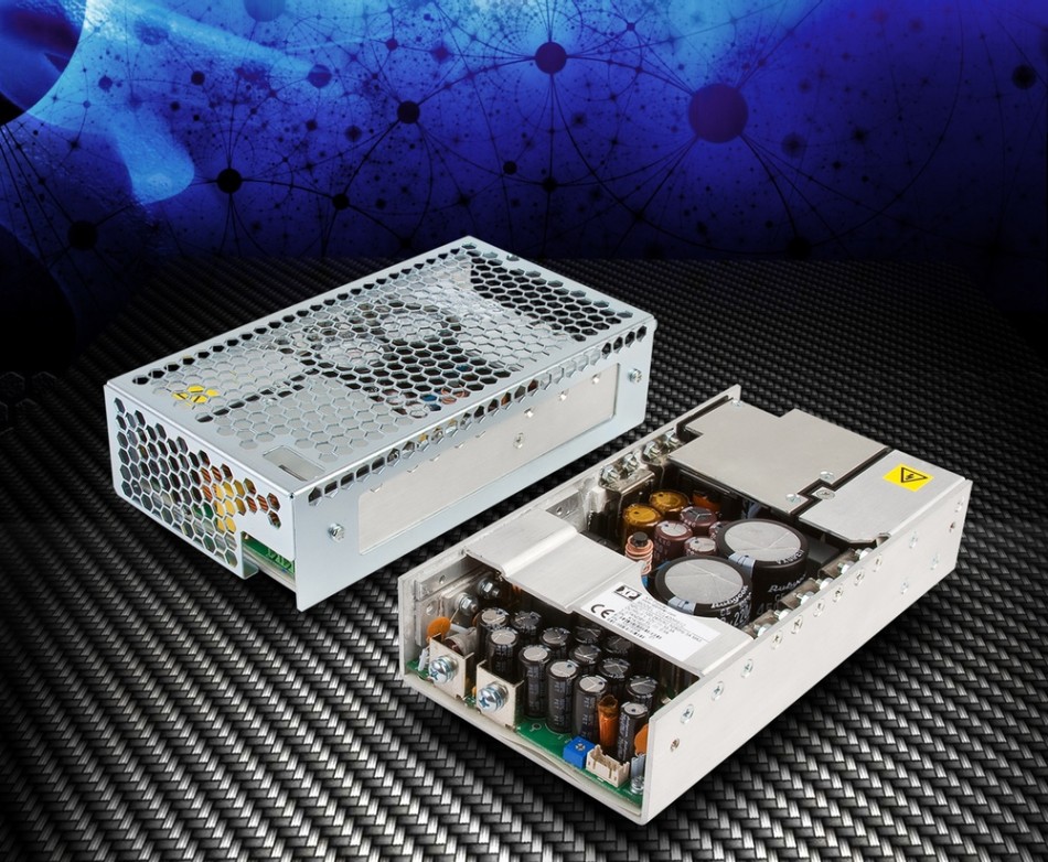
Image The XP CCL400 power supply, showing capacitors with the covered diode section towards the rear of the open-frame version
The heat from components such as the transformer turns out to be useful. The previous generation of AC/DC converters in the series used a bridgeless rectification scheme. “But that topology didn’t meet the cost targets we had, particularly when working with the new power-factor correction scheme we wanted to use. So we moved back to a bridge architecture using four diodes.
“With diodes if you run them hot the forward voltage drops, which gives a gain in terms of efficiency because you get less power loss. So, in this section we run the diodes about 20 per cent hotter than normal – if you run it hotter than that, that’s where it starts to impact reliability. Although it gives only milliwatts of gain, every little adds up. To get to 94 per cent efficiency you have the minimize the losses wherever you can.
“It’s a clever use of existing technology, with the engineer knowing how to extract every last bit of power saving out of the product,” said Head.
The capacitors on the other hand are not designed to heat up. “For a capacitor,” said Head. “There are two things that heat it up. One is the environment it’s in and we try to minimize that. The other thing is the self-heating of the capacitor. To reduce self heating you either have to reduce ripple or reduce ESR [effective series resistance]. It was much more cost effective to double up and change the effective ESR. We looked at adding inductors to reduce ripple but didn’t have the space. It looks weird but it works really well.”
Changes in capacitor technology have helped make an array of capacitors viable. “We put in high-lifetime capacitors. We investigated the cost of 2000-hour capacitor versus 5000 and 12,000-hour products and it made sense to use those longer-lifetime version. This supply only uses 5000-plus capacitors,” Head added. “Part of the situation is the arrival of new materials technologies, which are leading to higher lifetime so we are now looking at these for other products.”
Although the design relies on the flow of conducted and convected heat through and out of the product, XP’s lead designer on the product did not use thermal modeling. “He does a lot of prototyping,” Head explained.
