TSMC hints at glass interposer for mobile SoCs
Once upon a time, the interposer was seen as something of an interim technology, a stopping-off point on the way to through-silicon-via 3D stacks. But that isn’t stopping TSMC continuing to invest in the technique and broaden its appeal across a range of markets. The latest addition is mobile SoCs with the unveiling of a pathfinder glass-on-silicon carrier interposer at IEDM.
Current silicon interposers are not that attractive for high frequency RF applications. Silicon’s low resistivity raises concerns about power consumption and noise coupling performance. Glass represents an alternative building block for mobile integration on interposers.
The glass demonstrator described in Washington DC last week boasts far more attractive measurements for the quality factor (Q), power dissipation and power/signal integrity. It also represents a step forward for glass interposers generally. Taken together, these factors could map out a pre-3D TSV roadmap for heterogeneous HF designs, depending on how quickly TSMC now moves the technology to market.
Glass interposers have been reported previously, but the most recent benchmarks were for fabrication on 150mm wafers at 175um thickness with vias of 35um diameter and 50um pitch. TSMC’s work is on a 300mm wafer at 50um thickness (although this had to be increased to 100um to get the best metrics) with vias at 25um diameter and 45um pitch. It also uses a familiar process flow.
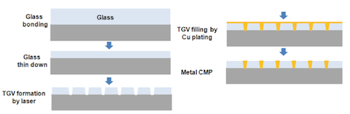
Fabrication flow for ultra-thin glass interposer (Source: TSMC/IEDM)
Interposer Q-factors
Q readings were taken by fabricating two test designs on the wafer. A 2D spiral inductor was fabricated on the 50um thick glass interposer. Its Q ranged from 27 to 30, against a range from 9 to 15 for a silicon equivalent. Increasing the thickness to upt to 100um allowed TSMC to implement a 3D embedded helical inductor, taking the Q range up to 56 to 63.
The extra thickness as well as the structure helped improve the results because towards 200um, the magnetic flux could be magnified within the same occupied area.
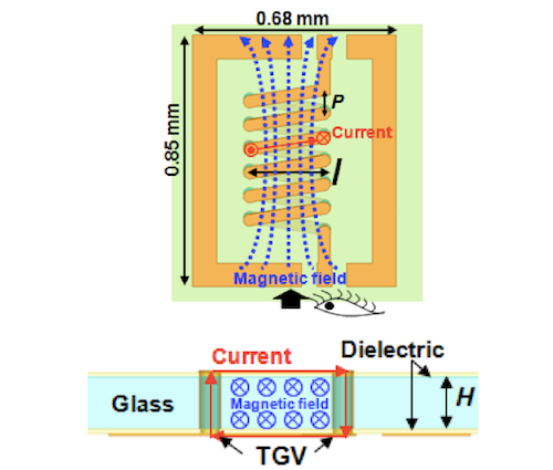
Schematic of 3D EHI and associated current / magnetic flow (Source TSMC/IEDM).
Interposer power and integrity data
The most significant readings for power and integrity were taken by implementing a WiFi system comprising baseband, RF and antenna.
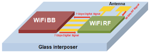
WiFi system on glass interposer (Source: TSMC/IEDM).
The 1mm GSG transmission line between the RF and antenna ran at 60GHz, with power loss at 14% for the glass interposer against 26.7% for the silicon interposer – a 48% improvement for the glass option. Fuller results are shown in this table.
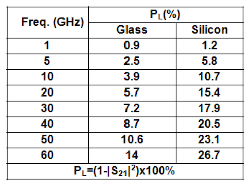
Power loss for WiFi system on glass and silicon interposers (Source:TSMC/IEDM)
The 1mm digital signal transmission line between the RF and baseband operated at the maximum available extraction rate of 7Gbps. Eye diagrams for the glass and silicon interposers, gave the glass implementation eye height of 598mV and jitter of 1.4ps against 328mV and 12.9ps for silicon.
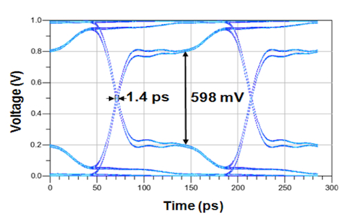
Eye diagram for WiFi system on glass interposer (Source: TSMC/IEDM)
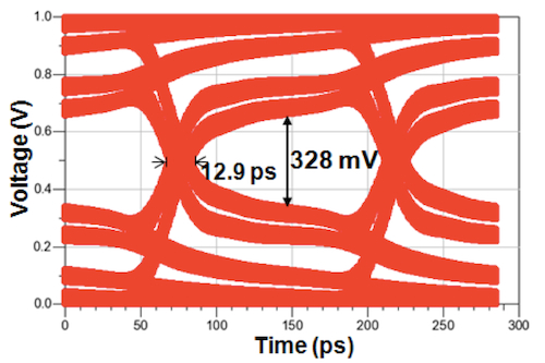
Eye diagram for WiFi system on silicon interposer (Source: TSMC/IEDM)
For now, TSMC is stressing that the technique is “promising” and nothing more. However, it adds another demonstrator to the foundry’s interposer campaign. Moreover, as noted by Qualcomm’s Geoffrey Yeap in his keynote, potential customers see interposer as as much of an option as other integration technologies.
